
Quick two-way stop valve

A stop valve, fast technology, applied in the direction of valve lift, valve details, valve device, etc., can solve the problems of high sealing body requirements, strong sealing surface pressure, long action time, etc., to ensure the shut-off effect and extend the service life The effect of life and acceleration improvement

Active Publication Date: 2018-12-04
SICHUAN LIDI VEHICLE CHASSIS TECH CO LTD
View PDF6 Cites 0 Cited by
  • Summary
  • Abstract
  • Description
  • Claims
  • Application Information

AI Technical Summary

Problems solved by technology

Although the former can realize the sealing of two-way air flow in the pipeline, the sealing ring will be squeezed out when the valve is closed to open due to the excessive pressure difference between the inlet and exhaust ports, and generally can only withstand the pressure of not more than 2mpa after shutting off. Differential pressure, suitable for low pressure gas control
Although the end face sealing method can withstand high pressure, but because when the diameter increases, the driving force required to lift the valve stem to open the valve increases greatly, and at the same time, when the valve is closed, the valve stem bears the effect of gas pressure. The pressure on the sealing surface is very high, the requirements for the sealing body are very high, and the service life is not long
Due to the influence of the above factors, the pilot drive mode is generally adopted for the high and low pressure valves with large diameters, but the following is that the action time is relatively long.

Method used


Image

  • Quick two-way stop valve

Examples


Embodiment Construction

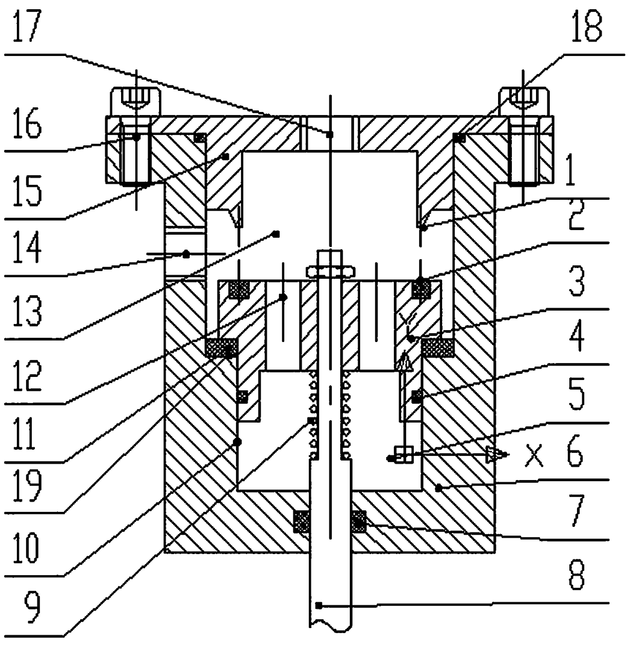
[0028] A fast two-way stop valve, including a valve body 6, an end cover 15 and a valve stem 8, wherein the positional relationship and connection relationship of each component are as follows (such as figure 1 shown):

[0029] The end cover 15 is fixed on the upper part of the valve body 6 by fastening bolts 16 , and a sealing ring 18 is arranged between the end cover 15 and the valve body 6 , so that an airtight air chamber is formed between the end cover 15 and the valve body 6 .

[0030] The end cover 15 is provided with an extending portion whose outer diameter matches the inner diameter of the valve body 6, and the outer diameter of the lower end of the extending portion decreases gradually. When the inner diameter of the inlet is close, the sealing lip 1 of the tapered structure is formed.

[0031]A valve plug 3 for dividing the inside of the valve body 6 into an upper air chamber 13 and a lower air chamber 5 is movable inside the valve body 6, and an air hole communic...


PUM


Abstract

The invention discloses a rapid double-direction stop valve. The rapid double-direction stop valve comprises a valve body, an end cover and a valve rod. The end cover is fixed to the upper portion of the valve body, a seal lip stretching into the valve body is arranged on the end cover, a valve plug for dividing the interior of the valve body into an upper gas chamber and a lower gas chamber is movably arranged in the valve body, a gas hole communicating the upper gas chamber with the lower gas chamber is formed in the valve plug, and the valve rod stretches into the valve body from the lower portion of the valve body to be fixedly connected with the valve plug; a first gas opening communicated with the upper gas chamber is formed in the valve body, and a second gas opening communicated with the upper gas chamber is formed in the end cover; and the valve plug and the seal lip are matched to control the first gas opening and the second gas opening to be on and off. When the stop valve is opened and closed, axial pressure borne by the valve plug is reduced, opening and closing of the stop valve can be rapidly achieved through small driving force, and the service life of the valve plug is prolonged.

Description

technical field [0001] The invention belongs to the field of air control engineering, and in particular relates to a fast two-way stop valve, which is suitable for connection control between various air chambers of vehicle air springs. Background technique [0002] To automatically control the on-off of pipelines connecting two containers with different pressures, electric, pneumatic or hydraulic pressure is almost always used as the power source to control the stop valve valve. Most of the time, the airflow direction is almost certain, that is The gas flows from the A container through the valve into the B container. Under such conditions, it is not difficult to realize the shut-off and good sealing of the valve. However, traditional gas valves generally use the axial displacement of the valve stem with the sealing ring to cooperate with the groove and sealing pair of the valve body to shut off the gas path, or use the end surface of the sealing body to cover the vent hole ...

Claims


Application Information

Patent Timeline
Patent Type & Authority Patents(China)
IPC IPC(8): F16K1/00F16K1/42F16K27/02F16K27/08F16K41/06
CPCF16K1/00F16K1/427F16K27/02F16K27/08F16K41/06
Inventor 杨德君
Owner SICHUAN LIDI VEHICLE CHASSIS TECH CO LTD
Learn More