A method to effectively ensure the normal braking of hydraulic motor drive

A hydraulic motor and normal braking technology, which is applied in the direction of servo motors, servo motor components, fluid pressure actuators, etc., can solve the problems of high oil return back pressure in the hydraulic system, brakes that cannot brake normally, etc., and achieve the elimination of back pressure Affect, ensure normal braking and work, overcome the effect of abnormal braking

Active Publication Date: 2018-02-02
安徽环球传动科技有限公司
View PDF10 Cites 0 Cited by
  • Summary
  • Abstract
  • Description
  • Claims
  • Application Information

AI Technical Summary

Problems solved by technology

[0007] The purpose of the present invention is to overcome the problem that the brake cannot perform normal braking due to the excessively high oil return back pressure of the hydraulic system when the existing hydraulic motor drive adopts gears for transmission, and to provide a method that can effectively ensure the normal braking of the hydraulic motor drive. method

Method used


Image

  • A method to effectively ensure the normal braking of hydraulic motor drive
  • A method to effectively ensure the normal braking of hydraulic motor drive
  • A method to effectively ensure the normal braking of hydraulic motor drive

Examples


Embodiment 1

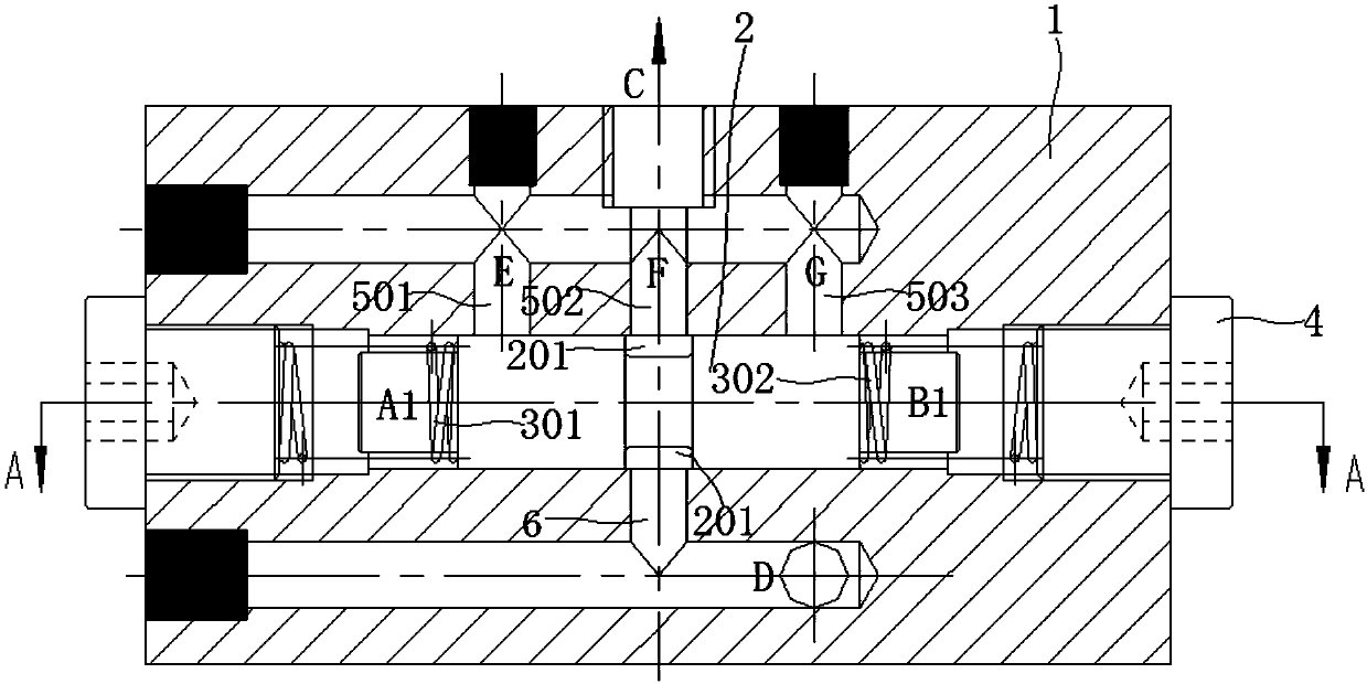
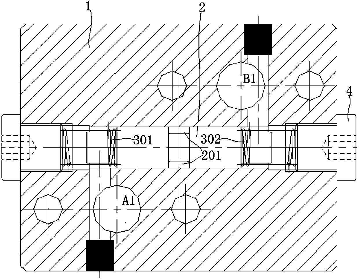
[0042] Such as figure 1 , figure 2 As shown, a shuttle valve with a neutral unloading function in this embodiment includes a valve body 1 and a valve core 2. The valve body 1 is provided with a valve cavity inside, and the valve core 2 is located inside the valve cavity and can move along the valve body. The cavity moves left and right; the left and right ends of the valve cavity communicate with the first oil inlet A1 and the second oil inlet B1 respectively through the oil inlet, the above oil inlet is vertically arranged with the valve cavity, and the valve cavity The top of the tank is connected with the oil outlet C through the oil outlet, and the oil outlet C is connected with the brake acting on the hydraulic motor through the pipeline. In this embodiment, the bottom of the valve cavity is provided with an oil return passage 6, and the middle part of the valve core 2 is processed with a stepped groove 201 (that is, the valve core 2 is processed into a stepped cylindri...

Embodiment 2

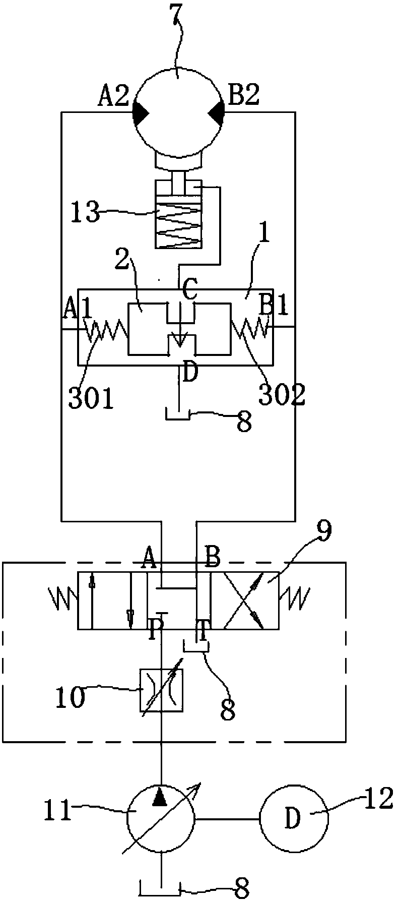
[0045] Such as Figure 1-3 As shown, a shuttle valve with a neutral unloading function in this embodiment includes a valve body 1 and a valve core 2. The valve body 1 is provided with a valve cavity inside, and the valve core 2 is located inside the valve cavity and can move along the valve body. The cavity moves left and right; the left and right ends of the valve cavity communicate with the first oil inlet A1 and the second oil inlet B1 respectively through the oil inlet, and the above oil inlet and the valve cavity are vertically arranged, so that on the one hand it can Oil can be fed into the valve chamber of the shuttle valve through the first oil inlet A1 and the second oil inlet B1; Oil ports A2 and B2 enter oil. The top of the valve cavity communicates with the oil outlet C through the oil outlet, and the oil outlet C is connected with the brake acting on the hydraulic motor through the pipeline. In this embodiment, the bottom of the valve cavity is provided with an ...


PUM


Abstract

The invention discloses a method for effectively guaranteeing normal braking of hydraulic motor drive, and belongs to the technical field of hydraulic motor drive braking. According to the method for effectively guaranteeing normal braking of hydraulic motor drive, braking of a hydraulic motor is controlled through a hydraulic motor braking system, the top of a valve cavity of a shuttle valve in the braking system is communicated with an oil outlet C through an oil outlet channel, an oil return channel is arranged at the bottom of the valve cavity, a through hole distributed in the vertical direction is machined in a valve element, and elastic reset devices are arranged at the left end and the right end of the valve element. When a hydraulic system stops supplying oil, the valve element can be forced to reset through the elastic reset devices, and therefore the oil outlet channel, the through hole and the oil return channel are communicated to form an unloading channel of the shuttle valve. By means of the method, the shuttle valve can discharge pressure according to requirements, therefore, normal braking of a brake can be guaranteed, and hydraulic motor gear drive works normally.

Description

technical field [0001] The invention belongs to the technical field of hydraulic motor drive braking, and more specifically relates to a method for effectively ensuring normal braking of hydraulic motor drive. Background technique [0002] With the rapid development of the economy, sawmills and related factories mainly use wood grabbers to transport wood. Wood grabbers are important mechanical equipment in wood loaders. The performance of wood grabbers directly affects the work efficiency of wood grabbing. . The existing wood grab mainly includes two kinds of mechanical structure and hydraulic type. The mechanical type is driven by the mechanical transmission between the parts to close or open the wood grab. Thereby controlling the movement of the wood grab and greatly reducing the transmission of parts. [0003] The hydraulic rotary log grab usually drives the grab bucket to rotate through the rotary drive device during the working process, while the rotary drive of the e...

Claims


Application Information

Patent Timeline
Patent Type & Authority Patents(China)
IPC IPC(8): F15B11/08F15B13/04F15B15/22
CPCF15B11/08F15B13/04F15B15/22
Inventor 谷从余
Owner 安徽环球传动科技有限公司
Why Eureka
Try Eureka