A hydraulic push steel emergency stop device for a heating furnace

A technology of heating furnace and hydraulic pressure, which is applied in the field of hydraulic pusher for steel rolling pusher type heating furnace, which can solve the problems that the pusher cannot stop pushing steel, cannot meet the actual application requirements, and the valve is not completely closed, so as to achieve disassembly, assembly and maintenance Easy to replace, avoid damage to the furnace wall, and ensure continuous effectiveness

Active Publication Date: 2017-10-03
JIANGSU YONGGANG GROUP CO LTD
View PDF4 Cites 0 Cited by
  • Summary
  • Abstract
  • Description
  • Claims
  • Application Information

AI Technical Summary

Problems solved by technology

However, in actual use, it is found that sometimes the PLC has received an emergency stop signal, but the solenoid valve controlling the action of the hydraulic valve is still energized, and the solenoid valve coil is de-energized but the valve is not completely closed. Still can't make the steel pusher stop pushing steel when stopped
The entire steel pushing process involves multiple mechanisms such as the controller, the actuator, and the controlled object. The above-mentioned ordinary emergency stop method only stops at the controller level and cannot meet the actual application requirements.

Method used


Image

  • A hydraulic push steel emergency stop device for a heating furnace
  • A hydraulic push steel emergency stop device for a heating furnace
  • A hydraulic push steel emergency stop device for a heating furnace

Examples


Embodiment Construction

[0020] In order to deepen the understanding and recognition of the present invention, the present invention will be further described and introduced below in conjunction with the accompanying drawings.

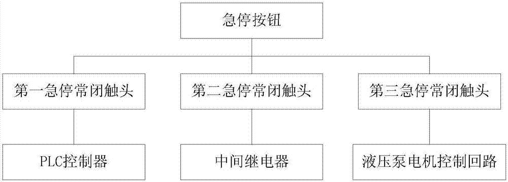
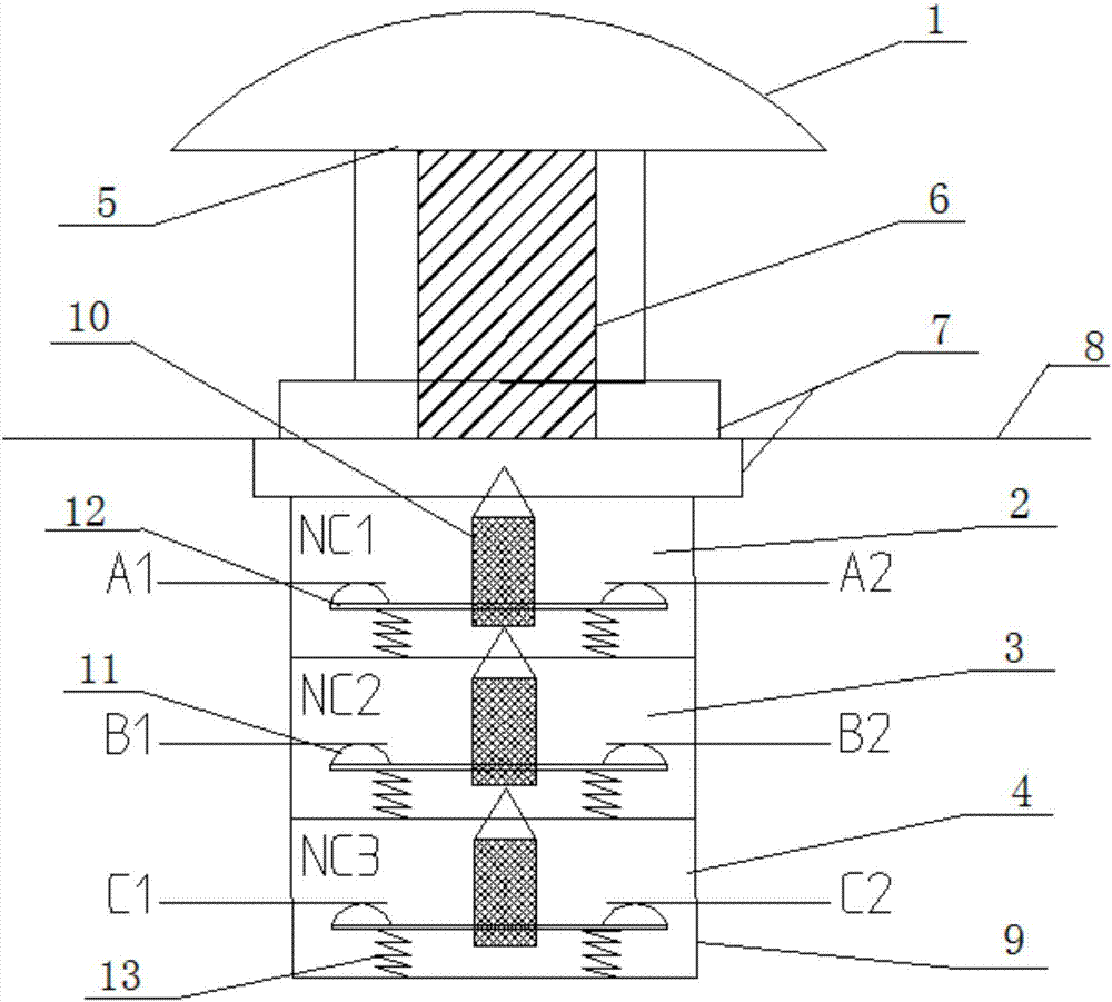
[0021] Such as figure 1 and 5 As shown, a heating furnace hydraulic pushing steel emergency stop device includes a PLC controller, an intermediate relay for controlling the on-off of the solenoid valve, a steel pushing machine hydraulic pump motor control circuit and an emergency stop button 1, and the emergency stop button 1 There is a button cap 5, a button push rod 6, an emergency stop button base 7, a first emergency stop normally closed contact 2, a second emergency stop normally closed contact 3 and a third emergency stop normally closed contact 4. The button cap 5 is fixedly connected to the top of the button push rod 6, the emergency stop button base 7 is arranged on the bottom of the button push rod 6, the first emergency stop normally closed contact 2, the second em...


PUM


Abstract

The invention relates to a hydraulic steel pushing scramming device for a heating furnace. The hydraulic steel pushing scramming device comprises a PLC, an intermediate relay for controlling a solenoid valve, a hydraulic pump motor control loop and a scramming button. A button cap, a button ejector rod, a scramming button base, a first scramming normally-closed contact, a second scramming normally-closed contact and a third scramming normally-closed contact are arranged on the scramming button. The button cap is fixedly connected to the top of the button ejector rod. The first scramming normally-closed contact, the second scramming normally-closed contact and the third scramming normally-closed contact are all connected with the scramming button base in series. The first scramming normally-closed contact is connected into a scramming signal input terminal on the PLC in series, the second scramming normally-closed contact is connected into the intermediate relay in series, and the third scramming normally-closed contact is connected into the hydraulic pump motor control loop in series. According to the hydraulic steel pushing scramming device for the heating furnace, through the three scramming normally-closed contacts arranged on the scramming button, the three-interactive steel pushing scramming effect is achieved, and continuous effectiveness of scramming in the steel pushing work is guaranteed.

Description

technical field [0001] The invention relates to the technical field of a hydraulic steel pusher for a steel rolling pusher type heating furnace, in particular to a heating hydraulic pusher emergency stop device for the steel pusher of a steel rolling pusher type heating furnace. Background technique [0002] The control system of the existing hydraulic steel pusher for the steel rolling heating furnace is usually composed of three parts, namely, the hydraulic pump (driven by a three-phase AC asynchronous motor) that provides stable hydraulic power, the solenoid valve that performs the steel pushing operation, and the operation command Programmable controller PLC. Among them, the emergency stop signal of the steel pushing action is generally controlled by the program inside the PLC. In order to make the steel pushing function stop in time when the steel is pushed in place during the feeding process of the stove (steel billet), it can prevent the stove from being jammed by exc...

Claims


Application Information

Patent Timeline
Patent Type & Authority Patents(China)
IPC IPC(8): C21D9/70C21D11/00
CPCC21D9/70C21D11/00
Inventor 王飞孙少斌王震江波周萍萍
Owner JIANGSU YONGGANG GROUP CO LTD
Why Eureka
Try Eureka