
Plastic bottle processing device for even forming

A technology for processing equipment and plastic bottles, which is applied in the field of plastic bottle molding, and can solve the problems of quality impact of finished products, inability to quickly cool down equipment life, and mixing of people

Inactive Publication Date: 2016-09-28
北京佑众全椒制药有限公司
View PDF0 Cites 1 Cited by
  • Summary
  • Abstract
  • Description
  • Claims
  • Application Information

AI Technical Summary

Problems solved by technology

[0002] With the rapid development of the economy, plastic packaging materials are used more and more widely, such as plastic bottles for filling milk. In the processing process, the plastic masterbatch must first be plasticized and extruded to form an intermediate product. The existing molding machine includes a main frame, a blow extrusion molding device, a mold opening and closing device, an electric control device, a hydraulic device, and a pneumatic device. The blow extrusion molding device is installed On the main frame, the mold opening and closing device is installed on the side of the main frame and corresponds to the blow extrusion device. The electric control device, hydraulic device and pneumatic device are respectively installed on the main frame. The blow extrusion device includes a feed hopper, a machine barrel, Screw, motor and extrusion die head, the screw is coaxially installed in the barrel and driven by a motor installed at one end of the barrel, the other end of the barrel is installed with an extrusion die head, the feed hopper is installed on the top of the barrel, the machine The outer wall of the barrel is equipped with a heating device, so that the plastic masterbatch melts into a viscous fluid state and enters the die to be extruded to become an intermediate product. Since the heating device is installed on the outer wall of the barrel to indirectly heat the masterbatch, it consumes a lot of energy, takes a long time, and reduces In addition, the cylinder and the screw cannot be cooled quickly during shutdown, which will have a certain impact on the life of the equipment. In addition, some impurities are sometimes mixed in the plastic masterbatch, which has a certain impact on the quality of the finished product.

Method used


Image

  • Plastic bottle processing device for even forming

Examples


Embodiment Construction

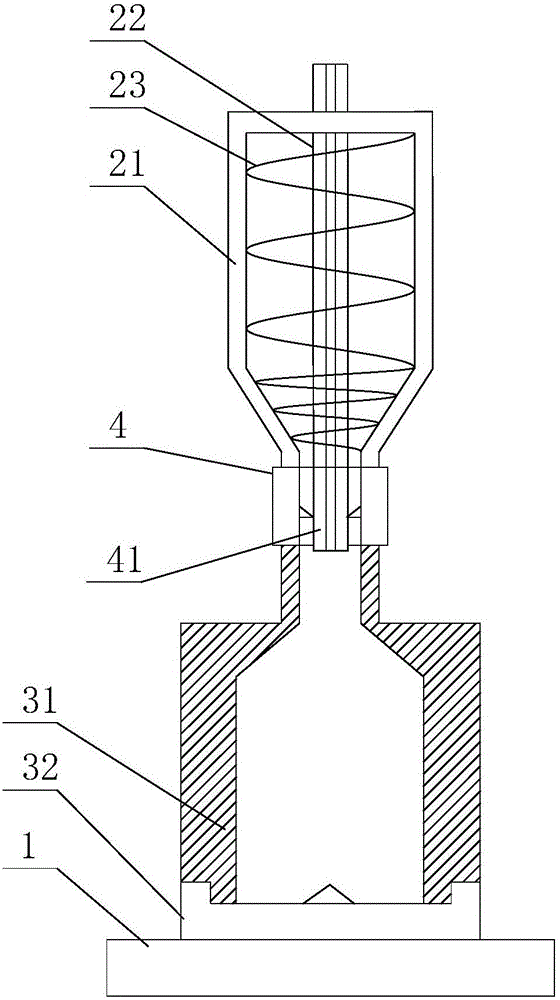
[0015] Such as figure 1 as shown, figure 1 It is a structural schematic diagram of a uniformly formed plastic bottle processing equipment proposed by the present invention.

[0016] refer to figure 1 , a uniformly formed plastic bottle processing equipment proposed by the present invention, comprising: a base 1, a feeding device, a mold assembly, a cutting device 4, a first driving device, and a second driving device;

[0017] Mold assembly comprises patrix 31, mold base 32, and mold base 32 is rotatably installed on the base 1 and its rotating shaft is vertically arranged, and the first driving device is connected with mold base 32 and is used to drive mold base 32 to rotate, and upper mold 31 is positioned at mold base. Above the base 32, a vertically extending molding cavity is formed between the upper mold 31 and the mold base 32, and the top of the molding cavity is provided with a first feed port;

[0018] The cutting device 4 is located above the upper mold 31, and t...


PUM


Abstract

The invention discloses a uniformly formed plastic bottle processing equipment. The mold base is rotatably installed on the base and its rotating shaft is vertically arranged. The upper mold is located above the mold base, and a vertically extending forming mold is formed between the upper mold and the mold base. cavity, the cutting device is located above the upper die, the cutting device is provided with a vertically penetrating cooling cavity, the cooling cavity is provided with an inner support tube, the inner wall of the cooling cavity is provided with a cutting piece, the barrel is located above the cutting device, A screw feeding mechanism is arranged in the barrel, and an air inlet cavity is arranged in the screw feeding mechanism, and the air inlet cavity communicates with the molding cavity through the cooling cavity. The uniformly formed plastic bottle processing equipment proposed by the present invention has an optimized and reasonable structural design. On the one hand, the screw feeding mechanism ensures uniform feeding of the blank during feeding; The inner molding is uniform, and it is convenient for the plastic bottle to be released from the upper mold after molding.

Description

technical field [0001] The invention relates to the technical field of plastic bottle forming, in particular to uniformly formed plastic bottle processing equipment. Background technique [0002] With the rapid development of the economy, plastic packaging materials are used more and more widely, such as plastic bottles for filling milk. In the processing process, the plastic masterbatch must first be plasticized and extruded to form an intermediate product. The existing molding machine includes a main frame, a blow extrusion molding device, a mold opening and closing device, an electric control device, a hydraulic device, and a pneumatic device. The blow extrusion molding device is installed On the main frame, the mold opening and closing device is installed on the side of the main frame and corresponds to the blow extrusion device. The electric control device, hydraulic device and pneumatic device are respectively installed on the main frame. The blow extrusion device incl...

Claims


Application Information

Patent Timeline
Patent Type & Authority Applications(China)
IPC IPC(8): B29C49/04B29C49/36B29C49/48B29C49/42B29L22/00
CPCB29C49/04B29C49/36B29C49/4205B29C49/4278B29C49/48B29C2049/4879B29L2031/7158
Inventor 陈光
Owner 北京佑众全椒制药有限公司
Learn More