Microstrip antenna and microstrip antenna array

A microstrip antenna and antenna input technology, applied in the field of antennas, can solve problems such as complex structural design of fixed equipment, sub-optimal layout, and increased structural complexity, so as to avoid limited transmission distance, reduce structural complexity, and avoid The effect of power dispersion

Active Publication Date: 2016-09-21
成都知纬科技有限公司
View PDF6 Cites 0 Cited by
  • Summary
  • Abstract
  • Description
  • Claims
  • Application Information

AI Technical Summary

Problems solved by technology

In order to meet the rotation range of the antenna, the structural design of the fixed equipment is very complicated, and sometimes even in order to avoid structural interference with other components during the rotation of the antenna, out of compromise considerations, either increase the volume of the equipment, or change other components on the equipment. The layout of the components, the changed layout of the components may not be the optimal layout, which may sacrifice some performance indicators of the equipment, or increase the complexity of the structure, resulting in an increase in equipment costs

Method used


Image

  • Microstrip antenna and microstrip antenna array
  • Microstrip antenna and microstrip antenna array

Examples


Embodiment approach

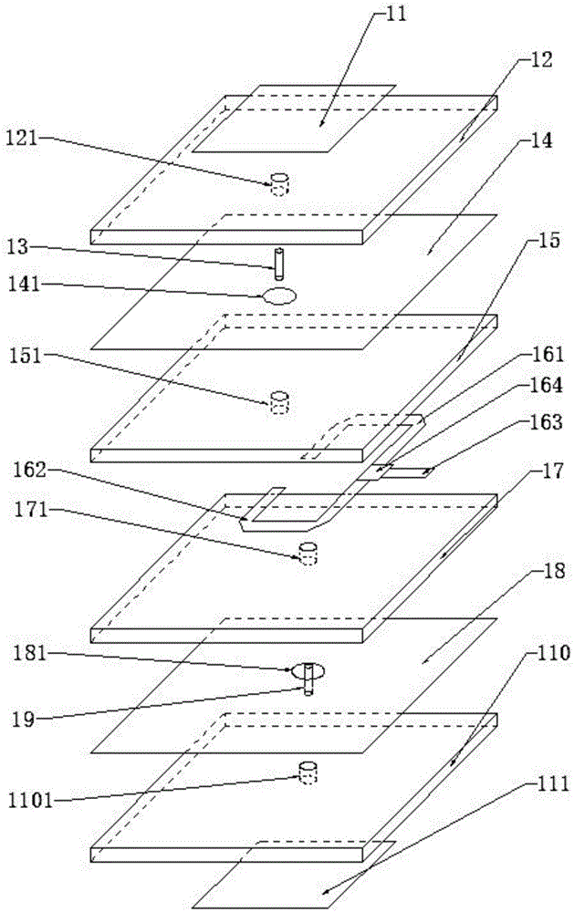
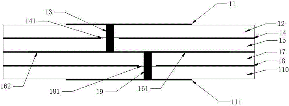
[0022] In order to realize two-way radiation, another embodiment can also be adopted: a microstrip antenna, including a first microstrip antenna body, a second microstrip antenna body and an antenna input and output interface network, and the antenna input and output interface network is connected with the first microstrip antenna at the same time. The microstrip antenna body communicates with the second microstrip antenna body, that is, the first microstrip antenna body and the second microstrip antenna body work simultaneously, and the first microstrip antenna body works to realize reception and transmission of signals in a predetermined space area, The work of the second microstrip antenna body can realize the reception and transmission of signals in another predetermined space area.

[0023] However, for this scheme, it was found during the experimental test that when the fixed device using the microstrip antenna of this scheme communicates with the moving target, compared ...


PUM


Abstract

The invention relates to the technical field of antennas, in particular to a microstrip antenna and a microstrip antenna array. The microstrip antenna comprises a first microstrip antenna body, a second microstrip antenna body, an antenna input and output interface network and a select switch, when the antenna input and output interface network communicates with the first microstrip antenna body through the select switch, the antenna input and output interface network is disconnected from the second microstrip antenna body; and when the antenna input and output interface network communicates with the second microstrip antenna body through the select switch, the antenna input and output interface network is disconnected the first microstrip antenna body. By the microstrip antenna provided by the embodiment of the invention, the rotating range of the antenna can be reduced by half in the azimuth plane of the antenna; a greater design convenience is provided for structural design of fixed equipment and layout of various components; the size of the fixed equipment can be reduced; the microstrip antenna can also communicate with a farther moving object; and the application scene is wider.

Description

technical field [0001] The invention relates to the technical field of antennas, in particular to a microstrip antenna and a microstrip antenna array. Background technique [0002] In the case of wireless communication between a fixed device and a moving target (such as a satellite), when the moving target moves out of the effective beam range of the antenna of the fixed device, the fixed device needs to adjust the beam pointing of the antenna to obtain communication with the moving target. At present, this type of fixed equipment usually uses directional antennas to communicate with moving targets. If the antenna beam is required to cover the hemispherical airspace, the antenna needs to achieve 360° rotation in azimuth and 0°~90° rotation in pitch. In order to meet the rotation range of the antenna, the structural design of the fixed equipment is very complicated, and sometimes even in order to avoid structural interference with other components during the rotation of the a...

Claims


Application Information

Patent Timeline
Patent Type & Authority Applications(China)
IPC IPC(8): H01Q1/50H01Q21/08
CPCH01Q1/50H01Q21/08
Inventor 殷忠良蔡朝国
Owner 成都知纬科技有限公司
Why Eureka
Try Eureka