
Multiple nano-rod dimer array structure, manufacture method thereof, method for exciting Fano resonance of multiple nano-rod dimer array structure, and optical sensor comprising multiple nano-rod dimer array structure

An array structure and nanorod technology, applied in the field of optical sensors, can solve problems such as asymmetry, limited parameters, and difficulty in preparation, and achieve the effects of stable resonance, strong resonance, and excellent performance

Inactive Publication Date: 2016-09-21
ZHENGZHOU UNIV
View PDF3 Cites 9 Cited by
  • Summary
  • Abstract
  • Description
  • Claims
  • Application Information

AI Technical Summary

Problems solved by technology

[0004] In metal nanostructures, the most effective way to excite Fano resonance is to generate perturbation in the plasmonic system. Typical stone table structures, non-concentric ring-disk structures, and various oligomer structures can achieve Fano resonance effects, but the above The structure is not symmetrical, so it is difficult to prepare, and the sensitivity of the prepared optical sensor is not high
[0005] The invention patent application with the publication number 104061997A discloses "a sensor based on the Fano resonance characteristics of the gold nanorod dimer array", which introduces the structural parameters and manufacturing method of the gold nanorod dimer, but does not have the parameters of the substrate To qualify, the described gold nanorod dimers can achieve Fano resonance
Due to the unreasonable determination of each parameter, its Fano resonance characteristics are not strong enough, and the parameters of the manufactured sensor are not good enough.

Method used


Image

  • Multiple nano-rod dimer array structure, manufacture method thereof, method for exciting Fano resonance of multiple nano-rod dimer array structure, and optical sensor comprising multiple nano-rod dimer array structure
  • Multiple nano-rod dimer array structure, manufacture method thereof, method for exciting Fano resonance of multiple nano-rod dimer array structure, and optical sensor comprising multiple nano-rod dimer array structure
  • Multiple nano-rod dimer array structure, manufacture method thereof, method for exciting Fano resonance of multiple nano-rod dimer array structure, and optical sensor comprising multiple nano-rod dimer array structure

Examples


Embodiment 1

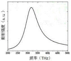
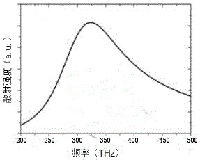
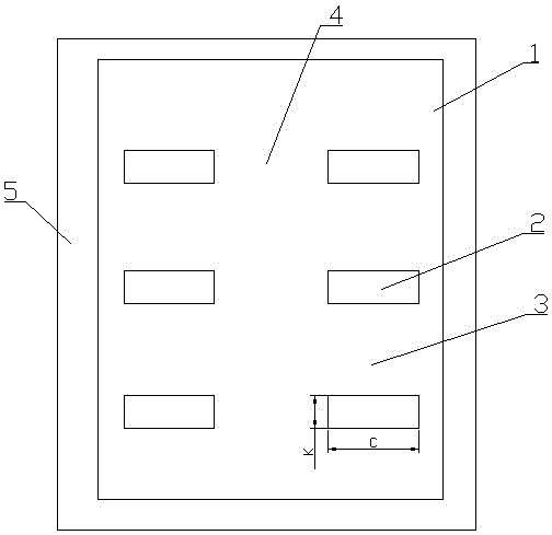
[0035] Example 1, such as image 3 The multiple nanorod dimer array structure shown includes a substrate 1 made of glass, and the refractive index of the substrate 1 is 1.5-1.9, preferably 1.5. There are three longitudinally arranged nanorod dimers on the substrate 1 in a vacuum environment. It is confirmed by experiments that when the number of nanorod dimers is 1 or 2, as figure 1 with figure 2 As shown, there is no phenomenon of quantum interference in the relationship between frequency and scattering intensity, and the Fano resonance characteristic of the multiple nanorod dimer array structure is not obvious. A longitudinal gap 3 is reserved between adjacent nanorod dimers. Because the number of nanorod dimers is 3, there are two longitudinal gaps 3 in total, and the lengths of the two longitudinal gaps 3 are equal, both 0 to 90 nm, preferably 70 nm. The nanorod dimer comprises two nanorods 2 with a lateral gap 4 reserved therebetween, and the material of the nanorods ...

Embodiment 2

[0043] Embodiment 2, the difference between this embodiment and Embodiment 1 is: the transverse gap 4 between the nanorods is equal, is 0 ~ 100 nm, preferably 20 nm; the length of each nanorod 2 is also equal, is 135 ~ 270 nm, preferably 190 nm; the longitudinal gap 3 between each nanorod dimer is not equal, but in the range of 0-90 nm. Such as Figure 8 As shown, when the longitudinal gap is changed, better Fano resonance can still be achieved.

Embodiment 3

[0044] Embodiment 3, the difference between this embodiment and embodiment 1 is: the longitudinal gap 3 between adjacent nanorod dimers is equal, is 0 ~ 90 nm, preferably 70 nm; the length of each nanorod 2 Also equal, 135-270 nm, preferably 190 nm; the lateral gap 4 between the nanorods is not equal, but in the range of 0-100 nm. Such as Figure 9 As shown, when the lateral clearance is changed, better Fano resonance can still be achieved.


PUM


Abstract

The invention discloses a multiple nano-rod dimer array structure, a manufacture method thereof, a method for exciting the Fano resonance of the multiple nano-rod dimer array structure, and an optical sensor comprising the multiple nano-rod dimer array structure. In the structure, appropriate refractive index, transverse gaps, longitudinal gaps and lengths are selected, such that the structure has good Fano resonance characteristics. Under the vertical effect of incident light with an electric field polarization direction parallel to a nano-rod long axis direction, the Fano resonance of the structure is strongly excited. With the structure, the sensitivity of the optical sensor can be greatly improved. Therefore, the invention has important influence on the improvement of the performance of optical sensors.

Description

technical field [0001] The invention belongs to the field of optical sensors, and in particular relates to a plurality of nanorod dimer array structures, a manufacturing method thereof, a method for exciting its Fano resonance and an optical sensor containing the same. Background technique [0002] The Fano resonance in the metal nanoplasmonic structure is analogous to the continuous excited state and the discrete excited state in the atomic system, constructing a broadband superradiation and a narrowband subradiation mode, and by tuning the frequencies of these two modes to overlap, make It can satisfy the condition of Fano resonance, that is, the constructive and destructive interference effect of plasmon hybrid mode. [0003] In recent years, the Fano resonance in plasmonic nanostructures and metamaterial structures has been extensively studied. The Fano resonance in nanostructures has a high quality factor, a large local field strength, and its resonance spectral charact...

Claims


Application Information

Patent Timeline
Patent Type & Authority Applications(China)
IPC IPC(8): B82B1/00B82B3/00B82Y30/00B82Y40/00G01J1/00
CPCB82B1/001B82B3/0014B82Y30/00B82Y40/00G01J1/00
Inventor 王俊俏张佳牧凯军臧华平范春珍陈述田勇志梁二军
Owner ZHENGZHOU UNIV
Learn More