Hydraulic support welding system and method

A technology of hydraulic support and welding system, applied in welding equipment, welding accessories, arc welding equipment, etc., can solve the problems of poor weld uniformity and consistency, difficult to guarantee production safety, and poor consistency of welded workpieces, and achieve uniformity. Good consistency, saving labor and time, and reducing the effect of location changes

Active Publication Date: 2015-12-02
SHANDONG ENERGY HEAVY EQUIP MFG GRP CO LTD +1
View PDF10 Cites 9 Cited by
  • Summary
  • Abstract
  • Description
  • Claims
  • Application Information

AI Technical Summary

Problems solved by technology

[0003] (1) The hydraulic support is essentially a multi-variety and small-batch product. If different types of products need to be welded by robots, different programs need to be compiled. The structural parts of the hydraulic support are of the lattice type, with many welds and complicated programming.
Robotic workstations are often in a state of constant programming with low equipment usage
[0004] (2) The assembly of hydraulic support connecting rods generally adopts the method of manual marking-this is also one of the biggest differences between the coal machinery industry and other machinery industries, and this characteristic of the industry leads to extremely poor consistency of the welded workpieces
A large number of deviation correction and positioning programs have to be added to the robot welding program, which further increases the programming workload and also causes the robot to continuously search for positions during the actual welding process and cannot continue to burn the arc
[0005] (3) The size and weight of the connecting rod of the hydraulic support are relatively large. At present, the existing robot welding test system adopts manual loading and unloading, and manual operation is required for workpiece turning. Not only the production efficiency is low, but also the production safety is difficult to guarantee.
[0006] (4) When welding a single connecting rod, use one welding robot to weld the two welds on the same side separately, which will cause poor uniformity and consistency of the welds on both sides, and are prone to defects and cracks Hidden danger

Method used


Image

  • Hydraulic support welding system and method
  • Hydraulic support welding system and method
  • Hydraulic support welding system and method

Examples


Embodiment 1

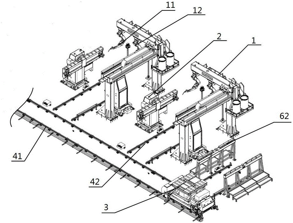
[0039] Such as figure 1 As shown, a hydraulic support welding system includes: 7 welding workstations 1, positioner 2, logistics trolley 3, guide rail, control system, loading rack 5, unloading rack, maintenance platform and safety fence, each welding The workstation 1 includes a welding robot 11, a welding robot 12 and a mobile arm. The welding robot 11 and the welding robot 12 are arc welding robots. The two welding robots are provided with their own independent welding systems. The welding robot 11 and the welding robot 12 are equipped with laser The tracking sensor can track and monitor the weld seam in real time, detect the actual shape of the weld seam, and eliminate the size and shape errors of the weld seam caused by processing, assembly and deformation of the workpiece. The welding robot 11 and the welding robot 12 are located on the moving arm, and the moving arm moves along a direction parallel to the guiding rail, driving two welding robots to move along this direc...


PUM


Abstract

The invention discloses a hydraulic support welding system and method. The hydraulic support welding system comprises at least one welding workstation, positioners, a logistics trolley, guide rails and a control system. Each welding workstation comprises two welding robots. The guide rails comprise the main guide rail and the auxiliary guide rails perpendicular to the main guide rail, the welding workstations are sequentially arrayed along the main guide rail, and the auxiliary guide rails are arranged between the positioners and the welding workstations. The welding workstations are provided with laser tracking sensors. The two welding robots of each welding workstation, the positioners and the logics trolley are connected with the control system. When the welding system and method are used for performing assembly welding on connecting rods, the model of the connecting rods is automatically recognized, so that the uniformity of welded joints is good.

Description

technical field [0001] The invention relates to the technical field of hydraulic support welding, in particular to a hydraulic support welding system and a welding method thereof. Background technique [0002] The connecting rod is an important part of the hydraulic support. The welding of the connecting rod belongs to the welding of medium and thick plates. Manual welding has been used for a long time. From a technical point of view, the application of automatic welding technology is hindered mainly by the following reasons: [0003] (1) The hydraulic support is essentially a multi-variety and small-batch product. If different types of products need to be welded by robots, different programs need to be compiled. The structural parts of the hydraulic support are of the lattice type, with many welds and complicated programming. Robotic workstations are often in a state of constant programming, with low equipment usage. [0004] (2) The assembly of hydraulic support connectin...

Claims


Application Information

Patent Timeline
IPC IPC(8): B23K9/02B23K9/32
CPCB23K9/0026B23K9/02B23K9/32
Inventor 李圣文任怀伟张延亮范正猛王海鹏李树国贾兆强赵国瑞曹成铭
Owner SHANDONG ENERGY HEAVY EQUIP MFG GRP CO LTD
Why Eureka
Try Eureka