A Configuration of Amphibious Air Cushion Rotorcraft

A technology of rotorcraft and configuration, applied in aircraft, convertible aircraft, air cushion and other directions, can solve the problems of mismatch between engine take-off power and cruising power, large resistance peak, etc., to improve the take-off performance from water and reduce water resistance. , the effect of strong environmental adaptability

Active Publication Date: 2018-05-01
CHINA ACAD OF AEROSPACE AERODYNAMICS
View PDF6 Cites 0 Cited by
  • Summary
  • Abstract
  • Description
  • Claims
  • Application Information

AI Technical Summary

Problems solved by technology

[0004] Technical problem solved by the present invention: In order to overcome the deficiencies of the existing amphibious aircraft technology, the present invention provides an amphibious air cushion rotor aircraft configuration, which solves the problem that the resistance peak of the conventional seaplane and ground-effect aircraft is too large during take-off, which causes the engine There is a serious mismatch between take-off power and cruising power. At the same time, it realizes the amphibious short-distance take-off and landing of the aircraft, as well as amphibious functions such as pad-lift navigation on the water surface, air cruise flight, and ground pad-lift travel.

Method used


Image

  • A Configuration of Amphibious Air Cushion Rotorcraft
  • A Configuration of Amphibious Air Cushion Rotorcraft
  • A Configuration of Amphibious Air Cushion Rotorcraft

Examples


Embodiment Construction

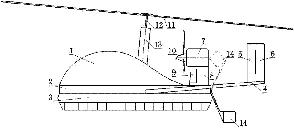
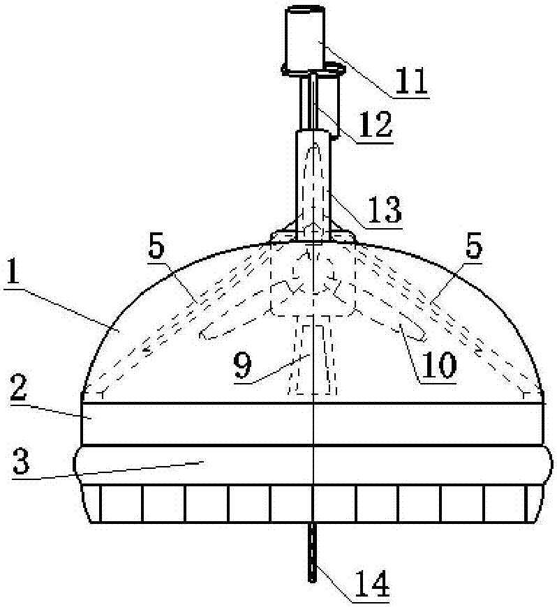
[0022] The invention provides an amphibious air cushion rotorcraft configuration, such as figure 1 , figure 2 , image 3 As shown, it includes: fuselage 1, fuselage bottom 2, apron 3, tail support 4, empennage 5, rudder 6, engine nacelle 7, nacelle support 8, pad lift damper 9, propeller 10, rotor 11, rotor Prop 12, prop fairing 13, water rudder 14.

[0023] Such as figure 1 As shown, the fuselage 1 is approximately half an ellipsoid according to the needs of the cabin capacity, the front part is raised in an arc shape, and the rear part is gradually tangent to the upper surface of the fuselage bottom 2; figure 2 As shown, the front part of the fuselage 1 is a semi-ellipse with a long-short axis ratio of 1.75 in the top view, and the rear part is a semi-elliptical shape with a long-short axis ratio of 1.3; the fuselage 1 is mainly used to accommodate personnel, materials, equipment, etc. 12 and strut fairing 13, and the transmission mechanism that arranges engine to roto...


PUM


Abstract

A triphibian air cushion rotor craft structure comprises a craft body (1), an apron (3), a propeller (10), a rotor (11) and the like. The craft body (1) is installed at the front end of a craft body bottom (2). The rotor (11) is supported on the craft body (1) through a rotor strut (12). The apron (3) is installed on the lower surface of the craft body bottom (2). Tail booms (4) are distributed on the two sides of the craft body bottom (2). A tail wing (5) is in an inverted V shape. Single-side wing face bottom ends are installed at the rear ends of the tail booms (4). A short cabin support (8) is supported between an engine short cabin (7) and the craft body bottom (2) and installed at the rear end of the craft body bottom (2). The propeller (10) is installed at the front portion of the engine short cabin (7). A water rudder (14) is connected to the tail end of the craft body bottom (2) through a rudderstock. By the adoption of the triphibian air cushion rotor craft structure, the problem that the engine take-off power and the cruise power are seriously unmatched is solved, water and land short-distance taking-off and landing of an aircraft are achieved, and the structure has the triphibian application purposes in water, on the land and in air.

Description

technical field [0001] The invention relates to a rotorcraft configuration. Background technique [0002] At present, the aircraft that can take off and land on water mainly include conventional seaplanes and ground-effect aircraft. The seaplane takes the domestic "Seagull 300" as an example. The aircraft is a fixed wing, the fuselage is a displacement hull form, the take-off weight is 1800kg, and a 228kW engine is arranged above the middle of the wing (cruise power 110kW). It is 479m, and it can also take off and land at the airport. The ground-effect aircraft takes the domestic "TY-1" type ground-effect aircraft as an example. This aircraft is a fixed wing with a small aspect ratio, and the fuselage is in the form of a displacement hull. The take-off weight is 4300kg. Two engines are arranged at the front ends of the wings on both sides. , the total power is 447.42kW (cruising power is 204kW), and the water takeoff distance is greater than 400m, which is only suitable fo...

Claims


Application Information

Patent Timeline
Patent Type & Authority Patents(China)
IPC IPC(8): B64C37/00B60F5/02B60V3/06B64C27/08
CPCB60F5/02B60V3/06B64C27/08B64C37/00
Inventor 李志国马存旺吴伟伟贾永清李广佳
Owner CHINA ACAD OF AEROSPACE AERODYNAMICS
Why Eureka
Try Eureka