Constant mesh gear speed change device
A constant meshing and gear technology is applied in the field of constant meshing gear shifting devices, which can solve the problems of large structure and difficult operation, and achieve the effects of compact structure, easy clutching and strengthening strength.
- Summary
- Abstract
- Description
- Claims
- Application Information
AI Technical Summary
Problems solved by technology
Method used
Image

Examples
Embodiment 1
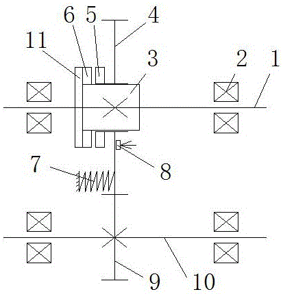
[0014] With reference to the attached drawings, a gear shifting device with constant meshing is provided with bearings 2 at both ends of the driving shaft 1 and the driven shaft 10, and a driven gear 9 is fixed on the driven shaft 10, and fixed on the driving shaft 1. A fixed sleeve 3 is provided, a clutch ratchet 6 of the fixed sleeve is provided at one end of the fixed sleeve 3, a driving gear 4 is set on the sleeve of the fixed sleeve 3, and a driving gear is arranged on the end face of the driving gear 4 The clutch pawl 5 of the driving gear, the driving gear 4 and the driven gear 9 are in a constant mesh state, and under the action of the spring 7, the clutch pawl 5 of the driving gear and the clutch ratchet 6 of the fixed sleeve are in a constant separation state. The shaft 1 rotates but the driving gear 4 does not rotate, and the driven gear 9 and the driven shaft 10 also do not rotate. Under the action of the external force pushing the shift fork 8, the clutch pawl 5 of...
Embodiment 2
[0016] With reference to the attached drawings, a gear shifting device with constant meshing is provided with bearings 2 at both ends of the driving shaft 1 and the driven shaft 10, and a driven gear 9 is fixed on the driven shaft 10, and fixed on the driving shaft 1. A fixed sleeve 3 is provided, a clutch ratchet 6 of the fixed sleeve is provided at one end of the fixed sleeve 3, a driving gear 4 is set on the sleeve of the fixed sleeve 3, and a driving gear is arranged on the end face of the driving gear 4 The clutch pawl 5 of the driving gear, the driving gear 4 and the driven gear 9 are in a constant mesh state, and under the action of the spring 7, the clutch pawl 5 of the driving gear and the clutch ratchet 6 of the fixed sleeve are in a constant separation state. The shaft 1 rotates but the driving gear 4 does not rotate, and the driven gear 9 and the driven shaft 10 also do not rotate. Under the action of the external force pushing the shift fork 8, the clutch pawl 5 of...
Embodiment 3
[0018] With reference to the attached drawings, a gear shifting device with constant meshing is provided with bearings 2 at both ends of the driving shaft 1 and the driven shaft 10, and a driven gear 9 is fixed on the driven shaft 10, and fixed on the driving shaft 1. A fixed sleeve 3 is provided, a clutch ratchet 6 of the fixed sleeve is provided at one end of the fixed sleeve 3, a driving gear 4 is set on the sleeve of the fixed sleeve 3, and a driving gear is arranged on the end face of the driving gear 4 The clutch pawl 5 of the driving gear, the driving gear 4 and the driven gear 9 are in a constant mesh state, and under the action of the spring 7, the clutch pawl 5 of the driving gear and the clutch ratchet 6 of the fixed sleeve are in a constant separation state. The shaft 1 rotates but the driving gear 4 does not rotate, and the driven gear 9 and the driven shaft 10 also do not rotate. Under the action of the external force pushing the shift fork 8, the clutch pawl 5 of...
PUM
| Property | Measurement | Unit |
|---|---|---|
| Outer diameter | aaaaa | aaaaa |
| Total length | aaaaa | aaaaa |
| Tooth height | aaaaa | aaaaa |
Abstract
Description
Claims
Application Information
 - R&D
- Intellectual Property
- Life Sciences
- Materials
- Tech Scout
- Unparalleled Data Quality
- Higher Quality Content
- 60% Fewer Hallucinations
Browse by: Latest US Patents, China's latest patents, Technical Efficacy Thesaurus, Application Domain, Technology Topic, Popular Technical Reports.
© 2025 PatSnap. All rights reserved.Legal|Privacy policy|Modern Slavery Act Transparency Statement|Sitemap|About US| Contact US: help@patsnap.com