Magnetic oxygen carbon tank integrated buffer device for trains
The technology of a magnetic oxygen carbon canister and a buffer device is applied in the directions of traction devices, railway car body parts, transportation and packaging, etc., which can solve the problems of difficulty in ensuring air circulation and purification in the carriage, complex structure of the buffer device, and poor air quality. Achieve the effect of reducing the probability of bacterial growth, saving complexity, and ensuring quality
- Summary
- Abstract
- Description
- Claims
- Application Information
AI Technical Summary
Problems solved by technology
Method used
Image

Examples
specific Embodiment approach 1
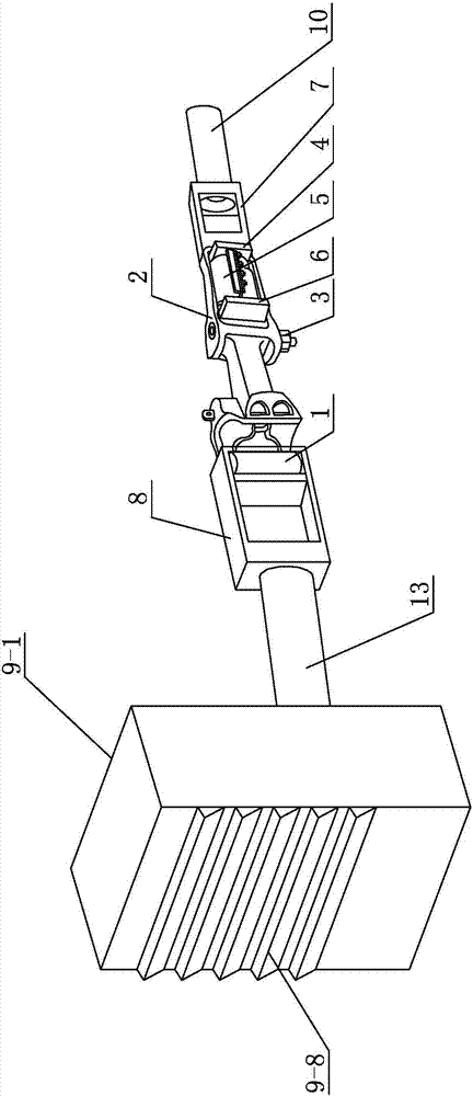
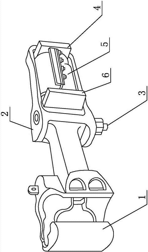
[0017] Specific implementation mode one: combine figure 1 , figure 2 , image 3 , Figure 4 and Figure 5 Describe this embodiment, this embodiment includes coupler 1, coupler frame 2, coupler pin 3, front slave plate 4, buffer 5, rear slave plate 6, front breather 7, rear breather 8 and magnetic oxygen carbon tank machine, the buffer 5 is arranged in the coupler frame 2, one end of the coupler 1 is the hanging end, the other end of the coupler 1 is a fixed end, and the fixed end of the coupler 1 is hinged by the coupler pin 3 In the coupler frame 2 and this end is connected with one end of the buffer 5 through the rear plate 6, the other end of the buffer 5 is fixedly connected with the inner wall of the coupler frame 2 through the front plate 4, and the front breather 7 is connected to the hook The outer wall of the tail frame 2 is fixedly connected, the hanging end of the coupler 1 is detachably connected with the front end of the rear breather 8, the magnetic oxygen c...
specific Embodiment approach 2
[0020] Specific implementation mode two: combination Figure 4 Describe this embodiment, the magnetic oxygen carbon canister machine described in this embodiment includes a shell 9-1, an air energy reactor 9-2, an ion group generator 9-3, a separation pump 9-4, and a magnetic energy reactor 9-5 , disc filter 9-6 and magnetic oxygen carbon tank group 9-7, described air energy reactor 9-2, ion group generator 9-3, separation pump 9-4, magnetic energy reactor 9-5, disc Type filter 9-6 and magnetic oxygen carbon canister group 9-7 are all arranged in the shell 9-1, and described shell 9-1 is provided with louver ventilation window 9-8 toward the end of train seat, and described air can react The air inlet of device 9-2 is connected with the rear end of rear breather 8, and the air outlet of air energy reactor 9-2 is connected with the air inlet of ion group generator 9-3, and the air outlet of ion group generator 9-3 is connected. The air outlet is connected with the inlet of the...
specific Embodiment approach 3
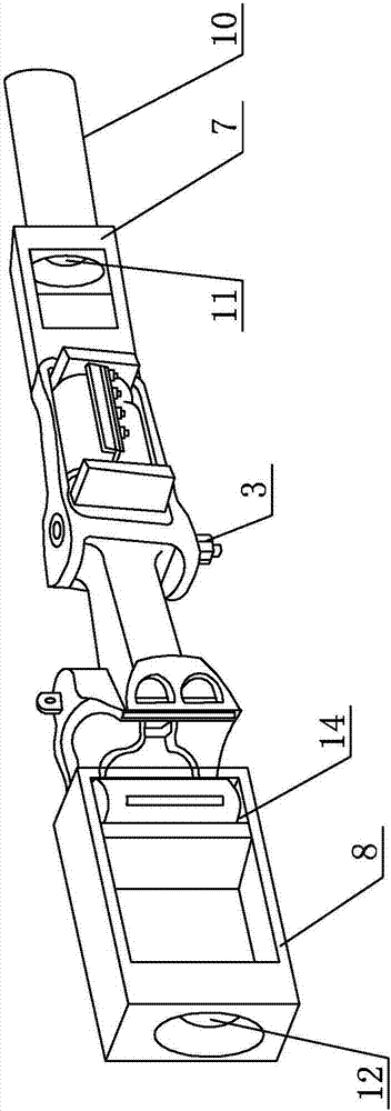
[0024] Specific implementation mode three: combination figure 1 , figure 2 and image 3 Describe this embodiment, the front breather 7 in this embodiment is a front fixed frame, the front fixed frame is a rectangular frame, the rear end plate of the front fixed frame is fixedly connected with the outer wall of the coupler frame 2, the The front end plate of the front fixed frame is processed with an exhaust hole 11, and the exhaust hole 11 communicates with the previous compartment in the train through the front connecting pipe 10.
[0025] In this embodiment, the front fixing frame is a rectangular frame with a simple structure, easy processing, and low manufacturing cost, which is beneficial to reduce the manufacturing cost of the present invention. The exhaust hole 11 in this embodiment is the exhaust gas discharged from the previous carriage in the train. Other unmentioned structures and connections are the same as those in the first or second embodiment.
PUM
 Abstract
Description
Claims
Application Information
 - Generate Ideas
- Intellectual Property
- Life Sciences
- Materials
- Tech Scout
- Unparalleled Data Quality
- Higher Quality Content
- 60% Fewer Hallucinations
Browse by: Latest US Patents, China's latest patents, Technical Efficacy Thesaurus, Application Domain, Technology Topic, Popular Technical Reports.
© 2025 PatSnap. All rights reserved.Legal|Privacy policy|Modern Slavery Act Transparency Statement|Sitemap|About US| Contact US: help@patsnap.com