a cutting robot

A cutting robot and cutting torch technology, applied in welding/cutting auxiliary equipment, auxiliary devices, gas flame welding equipment, etc., can solve the problems of lack of mature industrial equipment, etc., and achieve the effect of simple structure and convenient operation

Inactive Publication Date: 2018-05-11
青岛博捷环保工程有限公司
View PDF6 Cites 0 Cited by
  • Summary
  • Abstract
  • Description
  • Claims
  • Application Information

AI Technical Summary

Problems solved by technology

[0002] Cutting work is often encountered in industrial production, such as steel pipe cutting. At present, there is no mature industrial equipment in the automatic cutting of steel pipes to complete the corresponding work. Therefore, there is an urgent need for a device that can quickly and accurately complete the cutting work.

Method used


Image

  • a cutting robot
  • a cutting robot

Examples


Embodiment Construction

[0012] The present invention will be further described below in conjunction with specific embodiments. The exemplary embodiments and descriptions of the present invention are used to explain the present invention, but not as a limitation to the present invention.

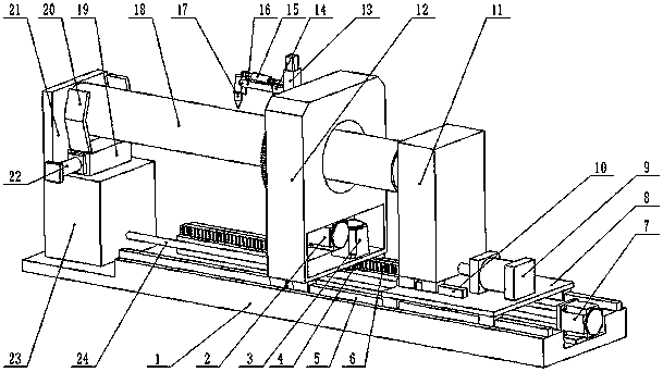
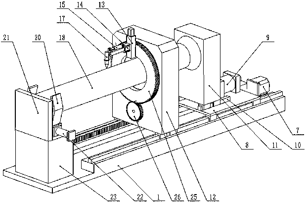
[0013] Such as figure 1 , figure 2 As shown, a cutting robot includes a base 1, a first moving motor 7 and a second moving motor 3, a rotating motor 2, a positioning seat 23 and a positioning plate 21, a centering clamping device 20 and a clamping cylinder 22, a clamping Mounting base 19, moving box 12 and jacking device 11, first slide rail 5 and second slide rail 10, torch 17 and torch motor 14, torch motor base 13, slide plate 8 and moving cylinder 9, moving gear 4 and moving rack 6, torch main gear 26 and torch slave gear 25, leading screw pair 24, torch connecting rod 16 and torch cylinder 15. The first slide rail 5 is installed on the base 1, the described positioning seat 23 is installed on the base 1, and...


PUM


Abstract

The invention discloses a cutting robot. The cutting robot comprises a base, a first moving motor, a second moving motor, a rotating motor and the like; a first sliding rail is mounted on the base; a locating seat is mounted on the base and located at the end of the first sliding rail; the first moving motor is mounted on the base, a lead screw pair is coaxially mounted on a main shaft of the first moving motor, and one end of the lead screw pair is mounted on the side face of the locating seat in a rotary manner; a moving rack is mounted on the first sliding rail; a moving box body is mounted on the first sliding rail in a sliding manner; a cylinder body of a cutting gun air cylinder is mounted on a cutting gun connection rod in a hinged manner, and the end of a piston rod of the cutting gun air cylinder is mounted on a cutting gun in a hinged manner; and a tightening mounting base is mounted above the locating seat, a cylinder body of a moving air cylinder is mounted on a sliding plate, and the end of a piston rod of the moving air cylinder and a tightly-bracing device are connected with each other. The cutting robot is provided with the adjustable cutting gun, so that the purpose of automated cutting is achieved; and the cutting robot is simple in structure and convenient to operate.

Description

technical field [0001] The invention relates to an automation equipment, in particular to a cutting robot, and belongs to the technical field of automation equipment. Background technique [0002] Cutting work is often encountered in industrial production, such as steel pipe cutting. At present, there is no mature industrial equipment in the automatic cutting of steel pipes to complete the corresponding work. Therefore, there is an urgent need for a device that can quickly and accurately complete the cutting work. Contents of the invention [0003] In view of the above problems, the present invention provides a cutting robot, which realizes the purpose of automatic cutting by being provided with an adjustable torch, has a simple structure and is easy to operate. [0004] The technical solution adopted by the present invention is: a cutting robot, including a base, a first moving motor and a second moving motor, a rotating motor, a positioning seat and a positioning plate, ...

Claims


Application Information

Patent Timeline
Patent Type & Authority Patents(China)
IPC IPC(8): B23K7/00B23K37/053B23K7/10B23K37/02B23K101/06
CPCB23K7/006B23K7/10B23K37/0229B23K37/0533B23K2101/06
Inventor 栾杰刘永川崔华忠
Owner 青岛博捷环保工程有限公司
Why Eureka
Try Eureka