
Control method of flow of reducing agent in flue gas SNCR denitration process

A control method and technology of reducing agent, which are applied in various fluid ratio control, non-electric variable control, ratio control and other directions, can solve the problem that the correction parameters do not meet the extreme working conditions, the cost is high, the first CEMS and the first ammonia meter Difficulty in selection, etc.

Active Publication Date: 2016-09-14
ENVIRONMENTAL SCI RES & DESIGN INST OF ZHEJIANG PROVINCE +1
View PDF3 Cites 9 Cited by
  • Summary
  • Abstract
  • Description
  • Claims
  • Application Information

AI Technical Summary

Problems solved by technology

[0004] However, there are three problems in the current reality: First, due to the harsh working conditions of the suitable monitoring point at the outlet of the C1 preheater: the flue gas temperature is as high as 320-350°C, the negative pressure can reach -6kPa, and the dust is as high as 100g / m 3 Above (coal-fired power plant 30g / m 3 high dust), the selection of the first CEMS and the first ammonia meter is difficult and the cost is high, and not all clinker line denitrification projects are equipped; second, even if the first CEMS and the first ammonia meter are equipped, due to the installation Poor working conditions, high failure rate of equipment, heavy meter maintenance workload, slight failure, and little value for data use; third, enterprises that actually configure SNCR denitrification systems, whether they are cement clinker production enterprises or thermoelectric boilers , Coal-fired power plants, under normal circumstances, CEMS and ammonia meters are only installed in the kiln tail chimney
[0005] In short, the SNCR flue gas denitrification system is different from the SCR flue gas denitrification system. Since there is no initial NOx concentration before the denitrification system, the flue gas parameters of the kiln tail chimney can only be used as the measurement basis, and the patent ZL2014 2 0199444.8 is used to calculate the ammonia flow rate. Once the assumed initial concentration is set, it will not be changed. In actual operation, due to the change of working conditions and the continuity of running time, the change of working conditions and fuel materials leads to the fact that the initial NOx concentration is constantly changing. Although the patent ZL2014 2 0199444.8 It is adjusted by K1 temperature correction parameter, K2 ammonia escape correction parameter, K3 is automatically generated by the ratio system (E / F) of theoretical denitrification rate and actual denitrification rate (E / F), these fine-tuning parameters are not adjusted in time when facing large fluctuations The problem
[0006] In addition, for individual initial NOx concentrations far beyond the design range (higher than 1000mg / m 3 or less than 300mg / m 3 ), because the regulating valve does not operate within the optimal opening range, resulting in anomalies in the history curve: for example, the NOx emission concentration after denitrification has been lower than the set target value, and the calculated ammonia flow rate is still higher than the actual ammonia flow rate, indicating that the original The correction parameters do not meet the extreme working conditions

Method used


Image

  • Control method of flow of reducing agent in flue gas SNCR denitration process
  • Control method of flow of reducing agent in flue gas SNCR denitration process
  • Control method of flow of reducing agent in flue gas SNCR denitration process

Examples


Embodiment 1

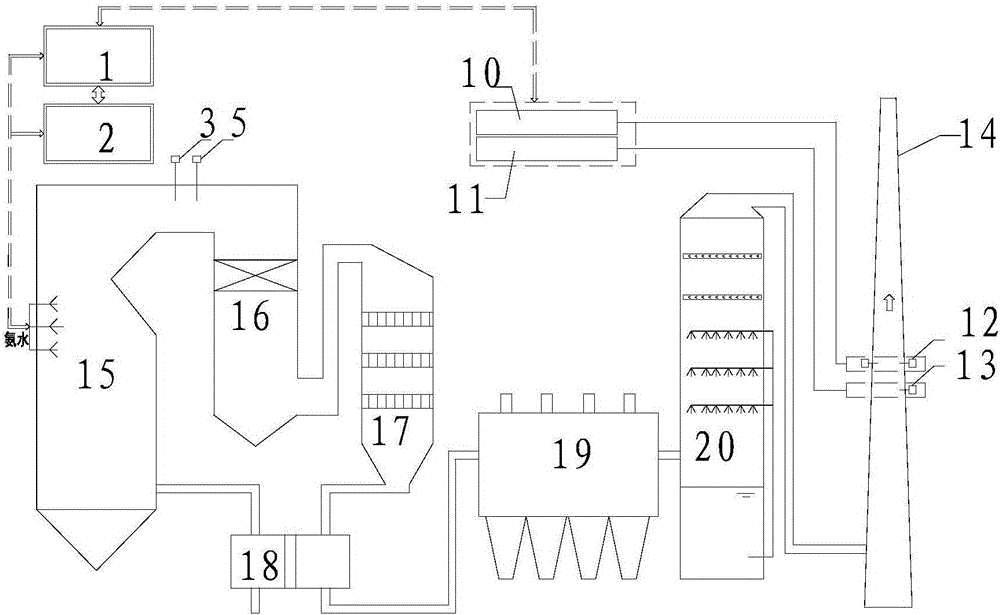
[0063] as attached figure 1 As shown, the specification is the SNCR denitrification reducing agent metering system for the calciner of the clinker production line with a daily output of 5000t, and ammonia water is used as the reducing agent. The decomposition furnace is equipped with a Pt100 temperature probe, and the outlet of the C1 preheater is equipped with a CO analyzer, and the signal is sent to the denitration system. The composition diagram of the denitration control system is as follows image 3 shown.

[0064] Before the construction of the denitrification device, due to the requirements of environmental protection supervision, a chimney CEMS was installed, and the flue gas indicators include: flue gas flow, NOx, SO 2 , dust, temperature, humidity, O 2 . When carrying out SNCR flue gas denitrification transformation, a chimney ammonia escape detector is added on the same floor as the chimney CEMS sampling probe, and all flue gas parameters are sent to the denitrif...

Embodiment 2

[0070] as attached figure 2 As shown, the SNCR denitrification reducing agent metering system of a circulating fluidized bed boiler (CFB) with a specification of 130 tons / hour uses ammonia water as the reducing agent. The furnace economizer is equipped with a Pt100 temperature probe and a CO analyzer, and the signal is sent to the denitrification system. The composition diagram of the denitrification control system is as follows image 3 shown.

[0071]Before the construction of the denitrification device, due to the requirements of environmental protection supervision, a chimney CEMS was installed, and the flue gas indicators include: flue gas flow, NOx, SO 2 , dust, temperature, humidity, O 2 . After the SNCR flue gas denitrification transformation, a chimney ammonia escape detector is added to the same platform as the chimney CEMS sampling probe, and all flue gas parameters are sent to the denitrification control system.

[0072] The input parameters for calculating th...


PUM


Abstract

The invention discloses a control method of a flow of a reducing agent in a flue gas SNCR denitration process. The reducing agent is sprayed into a flue gas, SNCR denitration is performed on the flue gas, and a nitrogen oxide in the flue gas is restored. The control method of the flow of the reducing agent in a denitration control system comprises the following steps: taking ammonia water as the reducing agent for example, a flue gas flow Q in a chimney and a nitrogen oxide concentration [NOx]2 in the chimney are acquired, and by use of a formula (1) shown in the descriptions, a reducing agent flow calculation value SV is calculated; and a determining formula is set according to the flow calculation value and an actually measured value, and through determining conditions, a denitration control system automatically adjusts an initial NOx concentration [NOx]1 and the reducing agent flow calculation value SV so as to enable the actually measured NOx concentration [NOx]2 to be continuously close to a target NOx concentration [NOx]3 and the actually measured flow of the reducing agent to be continuously close to a calculation flow.

Description

technical field [0001] The invention relates to a calculation method and control technology of a denitrification reducing agent, in particular to the reduction of selective non-catalytic reduction (selective non-catalytic reduction, SNCR) flue gas denitrification applied to cement clinker production lines, thermoelectric boilers, and coal-fired boilers The invention relates to a metering method of an agent, which belongs to the fields of environmental protection and chemical engineering automatic control. Background technique [0002] SNCR flue gas denitrification technology refers to spraying a reducing agent in a suitable temperature window under the action of no catalyst to reduce the nitrogen oxides in the flue gas into harmless water and nitrogen. It is the most widely used technology in flue gas denitrification projects of boilers and coal-fired power plants. [0003] Patent ZL2014 2 0199444.8 provides a reducing agent metering and control technology for SNCR flue gas...

Claims


Application Information

Patent Timeline
Patent Type & Authority Applications(China)
IPC IPC(8): G05D11/13B01D53/79B01D53/56
CPCB01D53/56B01D53/79B01D2251/2062G05D11/133
Inventor 周荣邵卫伟韦彦斐周敏捷许明海王恒管政
Owner ENVIRONMENTAL SCI RES & DESIGN INST OF ZHEJIANG PROVINCE
Learn More