Eureka AIR delivers breakthrough ideas for toughest innovation challenges, trusted by R&D personnel around the world.

Laser shock strengthening method for small-pitch gear surface

A laser shock strengthening and gear technology, applied in heat treatment equipment, furnaces, heat treatment furnaces, etc., can solve the problems of peeling, weakening the surface performance of the workpiece, and easy warping of the absorbing layer, so as to solve the problems of easy warping, easy cleaning, and improvement effect of effect

Inactive Publication Date: 2016-09-14
JIANGSU UNIV
View PDF7 Cites 8 Cited by
  • Summary
  • Abstract
  • Description
  • Claims
  • Application Information

AI Technical Summary

Problems solved by technology

But for spline punches and gear parts with small tooth pitch, the laser beam diameter is 2-8mm. When the spline punch or transmission gear tooth pitch is less than 10mm, the laser beam radiates to the side first, and the absorbing layer pasted on the side Absorbing laser energy produces gasification to form plasma, which shields the laser beam from radiating downward to the alveolar, and the alveolar part cannot be strengthened
In addition, when a large area is impacted, the absorbent layer in the overlapping area is prone to warping and peeling off
Therefore, the general laser shock peening method cannot realize the overall strengthening of the surface of such workpieces, which seriously weakens the performance of the workpiece surface after laser shock peening.

Method used


Image

  • Laser shock strengthening method for small-pitch gear surface
  • Laser shock strengthening method for small-pitch gear surface
  • Laser shock strengthening method for small-pitch gear surface

Examples


Embodiment Construction

[0027] The present invention will be further described below in conjunction with specific examples, but the protection scope of the present invention is not limited to the examples.

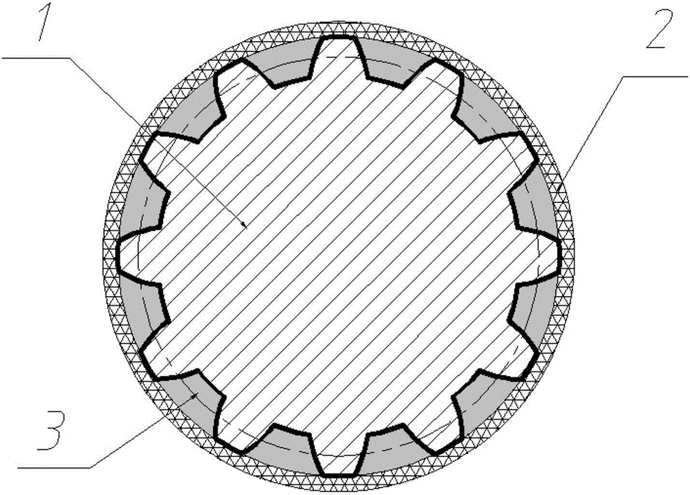
[0028] This embodiment adopts a small-pitch standard gear made of 304 stainless steel used at the engine end of an automobile, and its geometric dimensions are as follows: the number of teeth is 50, the modulus is 1 mm, and the pitch is 3 mm.

[0029] An example of using the above-mentioned workpiece for laser shock strengthening, the specific steps are:

[0030] (1) Mix PVC organic sol, acrylic synthetic resin and organic solvent thickener aluminum hydroxide in a certain proportion, and stir fully to form a uniform viscous transparent filling, and the components of the transparent filling The ratio by weight is: 70g of PVC organosol, 28g of acrylic synthetic resin, and 2g of organic solvent thickener.

[0031] (2) Put the above-mentioned transparent filler into a vacuum to discharge the air bub...


PUM

PropertyMeasurementUnit
thicknessaaaaaaaaaa
thicknessaaaaaaaaaa
diameteraaaaaaaaaa

Abstract

The invention relates to a laser surface shock strengthening technology, and in particular to a laser shock strengthening method for a small-pitch gear surface. The method can be expanded into surface strengthening of a small-pitch spline male die and a fine-pitch thread. The method is characterized in that clearances among teeth of a gear are filled with transparent fillers prepared by mixing materials in ratio, and the clearances are full of the transparent fillers in order to form a column body by the gear and the transparent fillers; then an aluminum foil is adhered to the column surface to be used as an energy absorbing layer; the gear surface can be subjected to large-area overlapping laser shock treatment under the condition that running water is used as a limiting layer. The method has the advantages that the clearances among the teeth of the gear are fully filled with the transparent fillers, and the tops of the teeth of the gear and the transparent fillers can form a smooth column surface, thus the large-area overlapping laser shock treatment can be conveniently carried out for the gear, and as a result, the laser shock strengthening effect can be greatly improved; and after the shock treatment, the transparent fillers in the clearances among the teeth of the gear can be easily removed, so that the demand of mass production can be met.

Description

technical field [0001] The invention relates to laser surface shock strengthening technology, in particular to a laser shock strengthening method for the surface of small pitch gears, and the method can be extended to the surface strengthening of small pitch spline punches and small pitch threads. Background technique [0002] Laser shock strengthening is a new type of surface strengthening technology. The super strong shock wave formed by the strong laser on the metal surface causes severe plastic deformation on the metal surface, induces deep residual compressive stress and refines the grains, and significantly improves the surface properties of metal parts. , compared with other technologies, it has high pressure (shock wave pressure reaches GPa-TPa level), high energy (peak power reaches GW level), ultra-fast (tens of nanoseconds) and ultra-high strain rate (up to 10 7 the s -1 ) four distinctive features, is one of the advanced manufacturing methods under extreme condi...

Claims


Application Information

Patent Timeline
Patent Type & Authority Applications(China)
IPC IPC(8): C21D10/00C21D9/32C21D1/68
CPCC21D1/68C21D9/32C21D10/005
Inventor 鲁金忠赵钊曹海迪
Owner JIANGSU UNIV
Why Eureka
Eureka Blog
Learn More