
Automatic correction device and method for focusing part of camera

An automatic calibration and camera technology, which is applied in the field of camera focusing, can solve problems such as product calibration errors, troubles for production enterprises, and high labor intensity of operators, and achieve the effects of reducing differences, improving quality, and increasing production capacity

Active Publication Date: 2016-09-07
ZHUHAI CITY GUANGHAOJIE PRECISION MACHINERY
View PDF5 Cites 8 Cited by
  • Summary
  • Abstract
  • Description
  • Claims
  • Application Information

AI Technical Summary

Problems solved by technology

At present, the calibration method of the camera focusing components on the market is: the pure manual focus calibration that has been used in the early days, using the artificial eye to judge the position, and manually calculating the data. Due to the limitation of the accuracy and speed of the human eye, some high-speed, high-precision The detection cannot be done manually at all, and the efficiency is low, the labor intensity of the operator is high, and it is easy to cause product correction errors
[0003] As production enterprises further increase the production efficiency requirements of camera testing equipment, the current situation of manual correction of camera focus efficiency has gradually troubled production enterprises

Method used


Image

  • Automatic correction device and method for focusing part of camera
  • Automatic correction device and method for focusing part of camera
  • Automatic correction device and method for focusing part of camera

Examples


Embodiment Construction

[0030] The idea, specific structure and technical effects of the present invention will be clearly and completely described below in conjunction with the embodiments and accompanying drawings, so as to fully understand the purpose, features and effects of the present invention. Apparently, the described embodiments are only some of the embodiments of the present invention, rather than all of them. Based on the embodiments of the present invention, other embodiments obtained by those skilled in the art without creative efforts belong to The protection scope of the present invention.

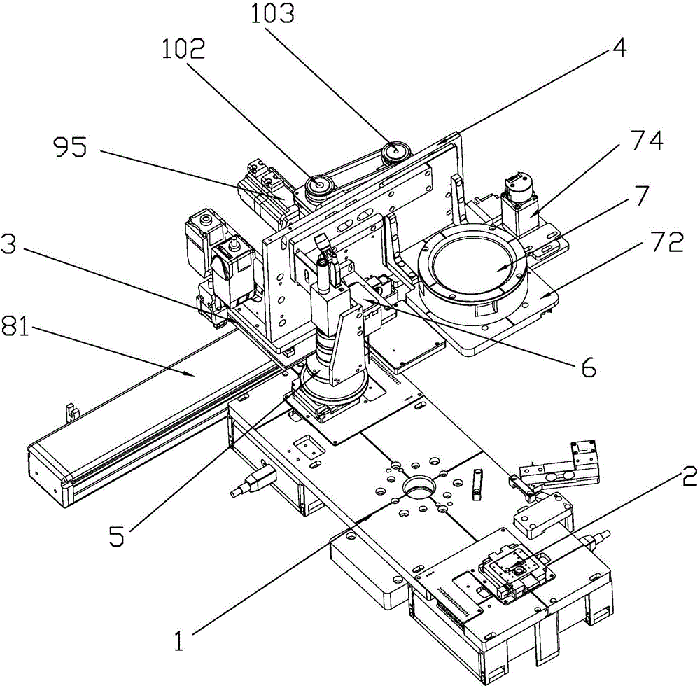
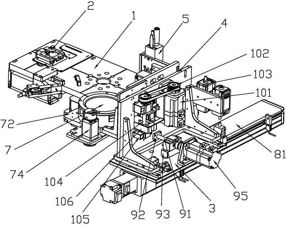
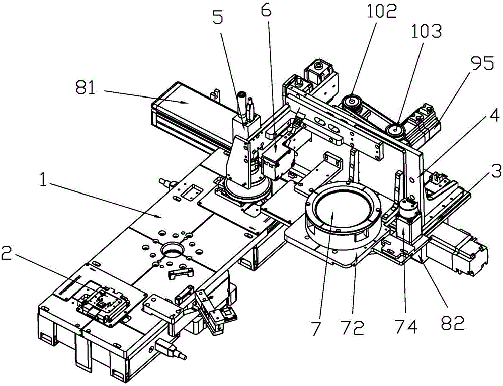
[0031] refer to Figure 1 to Figure 3 , an automatic calibration device for the focusing part of a camera, including a rotating platform 1, the rotating platform 1 is provided with a positioning hole, which is used to cooperate with the positioning pin for positioning before calibration, and reduce the error of position accuracy. The bottom of the rotary platform is provided with a rotary mechani...


PUM


Abstract

The invention discloses an automatic correction device and method for a focusing part of a camera. The device comprises a rotating platform, at least two camera module jigs are arranged on the rotating platform, a mounting table is arranged on one side of the rotating platform, a y-axis moving mechanism is arranged at the bottom of the mounting table, an x-axis moving mechanism is arranged on the mounting table, the x-axis moving mechanism comprises an x-axis mounting plate capable of moving along an x axis, an industrial camera and a height gauge are arranged on the x-axis mounting plate, the camera module jigs rotate to a position below the industrial camera during moving, a focusing head assembly is connected with a focusing u-axis mechanism and comprises a focusing head, the focusing head is arranged in parallel to the height gauge and the industrial camera, and the industrial camera, the height gauge and the focusing head are all electrically connected with a control host. The device and the method replace manpower to realize automatic correction of equipment, improve the productivity, reduce the difference among products, and thus improve the quality of the products.

Description

technical field [0001] The invention relates to the field of camera focusing, in particular to an automatic correction device and method for a camera focusing part. Background technique [0002] With the rapid development of the smart terminal industry in recent years and the popularity of video recording electronic products such as smartphones, tablet computers, and driving recorders, the market demand for cameras is increasing, which leads to the continuous expansion of camera manufacturers, and the demand for camera production equipment The volume is also growing. At present, the calibration method of the camera focusing components on the market is: the pure manual focus calibration that has been used in the early days, using the artificial eye to judge the position, and manually calculating the data. Due to the limitation of the accuracy and speed of the human eye, some high-speed, high-precision The detection cannot be done manually at all, and the efficiency is low, t...

Claims


Application Information

Patent Timeline
IPC IPC(8): H04N5/232H04N17/00
CPCH04N17/002H04N23/67
Inventor 杨海生
Owner ZHUHAI CITY GUANGHAOJIE PRECISION MACHINERY
Learn More