A new type of photoelectric musical instrument

A technology for optoelectronics and musical instruments, applied in the field of speakers, can solve the problems of low photoacoustic conversion efficiency, low irradiance, single optical frequency, etc., and achieve the effects of high photoacoustic conversion efficiency, prolonged service life, and good listening experience.

Active Publication Date: 2019-12-20
SUN YAT SEN UNIV
View PDF2 Cites 0 Cited by
  • Summary
  • Abstract
  • Description
  • Claims
  • Application Information

AI Technical Summary

Problems solved by technology

[0004] Compared with the wide application of photoacoustic phenomenon in scientific research occasions such as photoacoustic spectroscopy, photoacoustic microscopy and photoacoustic Doppler technology, there is a gap in the application of photoacoustic phenomenon in civilian applications, such as music performance. The reason is: on the one hand, the detection methods commonly used in civilian applications have low sensitivity and require strong environmental compatibility; on the other hand, the photoacoustic conversion efficiency in the photoacoustic effect is low, and it is difficult to produce obvious photoacoustic effect phenomena, resulting in High detection sensitivity is required, and it is best to work in a quiet place, which is obviously contrary to the requirements of civil places
[0005] Further analysis shows that the factors causing low photoacoustic conversion efficiency include: 1. The traditional photoacoustic effect uses sunlight, incandescent lamps, etc. as light sources, and their irradiance is low, and their luminous wavelength is inconsistent with the characteristic peak of the absorption spectrum of the absorbing layer; 2. , The sound cavity design needs to be improved
In addition, the light frequency emitted by sunlight and incandescent lamps is single, which also restricts the expansion of the photoacoustic effect in practical applications.

Method used


Image

  • A new type of photoelectric musical instrument
  • A new type of photoelectric musical instrument
  • A new type of photoelectric musical instrument

Examples


Embodiment 1

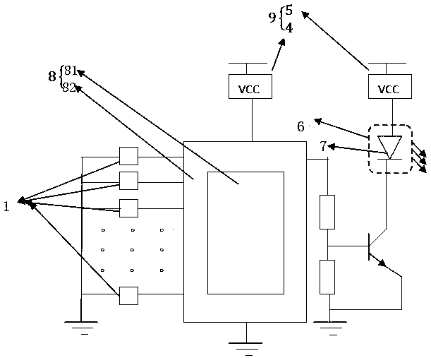
[0032] The structure diagram of a new type of photoelectric musical instrument in this embodiment is as Figures 1 to 3 As shown, it includes a power supply module 9, a control module 8, a light source 7, a sound module 6 and several scale volume input modules 1; the power supply module 9 is used to supply power to the control module 8 and the light source 7; the light source 7 and the sound The number of modules 6 is several, and the sound module 6 is used to convert the light emitted by the light source 7 into sound; the light source 7 and each scale volume input module 1 are respectively connected with the control module 8; trigger a scale volume input module 1 , the corresponding light source 7 emits light with a certain flicker frequency, and the sound module 6 converts the light emitted by the light source 7 into sound.

[0033]In this embodiment, the control module 8 includes a main control chip 81 and peripheral circuits 82 . A program is written in the main control c...

Embodiment 2

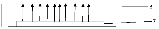
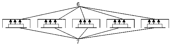
[0042] The difference between this embodiment and Embodiment 1 is that the size of the sound module 6 cavity is different. In this embodiment, the scale volume input module 1 has the same number as the sound module 6; different sizes can be customized according to the flicker frequency of the light source 7 The sound module 6, such as Figure 4 shown. With this setting, each semi-closed cavity can resonate with the corresponding scale, so as to emit a larger volume, so that people can have a better listening experience. When the control module 8 receives the signal input by the scale input button, it only needs to output a control command to the light source 7 in the corresponding sound module 6, so as to reduce the number of working light sources and save energy.

Embodiment 3

[0044] The difference between this embodiment and Embodiment 1 and Embodiment 2 is that the volume control method is different and the control module 8 is different. In this embodiment, the control module 8 also includes an AD conversion module 83, and the AD conversion module 83 Used to convert analog signals into electrical signals, such as Figure 6 As shown; the scale volume input module 1 includes a scale input button and a volume control button; the scale input button is provided with a pressure sensor 11, and the pressure sensor 11 is connected to the control module 8; the volume control button is a piano pedal structure. Such as Figure 7 As shown, it is a structural schematic diagram of the scale input button in this embodiment, including a cover plate 13, a scale button 12 and a pressure sensor 11, and the scale button 12 and the pressure sensor 11 are all located under the cover plate 13; Figure 8 As shown, it is a structural diagram of the volume input button in ...


PUM


Abstract

The invention relates to a loudspeaker which works by using a light intensity charge-induced sound generation phenomenon, specifically, relates to a novel photoelectric music instrument. The novel photoelectric music instrument includes a power supply module, a control module, light-emitting light sources, sound generation modules and a plurality of musical scale volume input modules; the power supply module is used for supplying power for the control module and the light-emitting light sources; a plurality of light-emitting light sources and a plurality of sound generation modules are adopted; the sound generation modules are used for converting light emitted by the light-emitting light sources into sound; and the light-emitting light sources and each musical scale volume input module are connected with the control module. When one musical scale volume input module is triggered, the module sends a musical scale input signal to the control module; the control module sends signals to a corresponding light source according to an instruction represented by the musical scale input signal, so that a corresponding light-emitting light source can emit light of a corresponding flicker frequency; and a corresponding sound generation module converts the light emitted by the light-emitting light source into sound. The opto-acoustic conversion efficiency of the novel photoelectric music instrument of the invention is high. The novel photoelectric music instrument can be utilized to achieve functions such as music instrument playing and opto-acoustic effect demonstration.

Description

technical field [0001] The present invention relates to a loudspeaker which utilizes the "light hearing phenomenon", and more particularly relates to a new type of photoelectric musical instrument. Background technique [0002] When a certain medium (such as carbon powder, etc.) is irradiated with light, the internal temperature of the medium will change due to the absorption of light by the medium, which will cause the structure and volume of the medium area to change, thereby pushing the air on the surface of the coal medium to expand. When the light intensity of the irradiation light source changes periodically, the temperature of the medium will rise and fall periodically, and cause the air layer on the surface of the medium to expand and contract synchronously, forming vibrations and radiating sound waves outward. This phenomenon is called audiophonic phenomenon, and it is widely used in the detection and evaluation of materials, medicine and other fields. [0003] Sin...

Claims


Application Information

Patent Timeline
Patent Type & Authority Patents(China)
IPC IPC(8): G10H1/02
CPCG10H1/02
Inventor 王嘉辉黄梓钊郭嘉阳薛钊鸿蔡志岗汤文龙洪伟槟
Owner SUN YAT SEN UNIV
Why Eureka
Try Eureka