
Magnetic resonance spectrometer and apparatus for controlling magnetic resonance spectrometer based on FPGA

A technology of magnetic resonance spectrometer and control device, which is applied in the direction of magnetic resonance measurement, etc., and can solve the problems of difficult application of time resolution, high cost, and low integration

Active Publication Date: 2016-09-07
UNIV OF SCI & TECH OF CHINA
View PDF6 Cites 5 Cited by
  • Summary
  • Abstract
  • Description
  • Claims
  • Application Information

AI Technical Summary

Problems solved by technology

In this type of design, each module uses its own clock reference source to achieve synchronization through asynchronous triggering, resulting in poor synchronization of the spectrometer, which is difficult to apply to occasions with high time resolution
In addition, the system has a lot of equipment, low integration, high cost, complex software and hardware, difficult to debug and difficult to maintain

Method used


Image

  • Magnetic resonance spectrometer and apparatus for controlling magnetic resonance spectrometer based on FPGA
  • Magnetic resonance spectrometer and apparatus for controlling magnetic resonance spectrometer based on FPGA
  • Magnetic resonance spectrometer and apparatus for controlling magnetic resonance spectrometer based on FPGA

Examples


Embodiment Construction

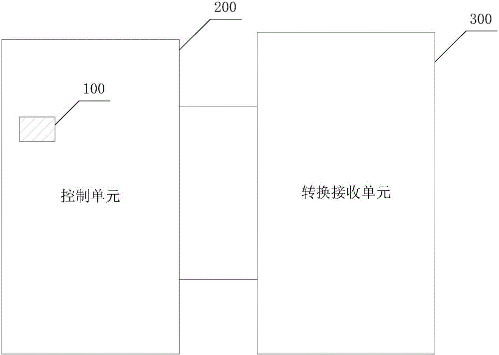
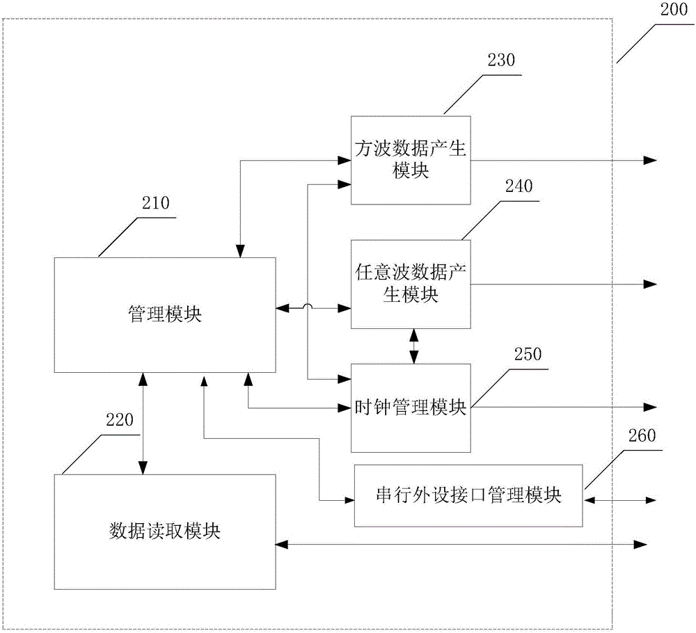
[0039] As described in the background technology, existing paramagnetic resonance spectrometers usually use independent arbitrary waveform generators, square wave generators, and data acquisition units to realize microwave generation and data acquisition, and realize the above-mentioned modules through the host computer software. control. In this type of design, each module uses its own clock reference source to achieve synchronization through asynchronous triggering, resulting in poor synchronization of the spectrometer, which is difficult to apply to occasions with high time resolution. In addition, the system has many devices, low integration, high cost, complex software and hardware, difficult to debug and difficult to maintain.

[0040] In view of this, an embodiment of the present invention provides an FPGA-based magnetic resonance spectrometer control device, which is applied to an electron paramagnetic resonance spectrometer, and the paramagnetic resonance spectrometer...


PUM


Abstract

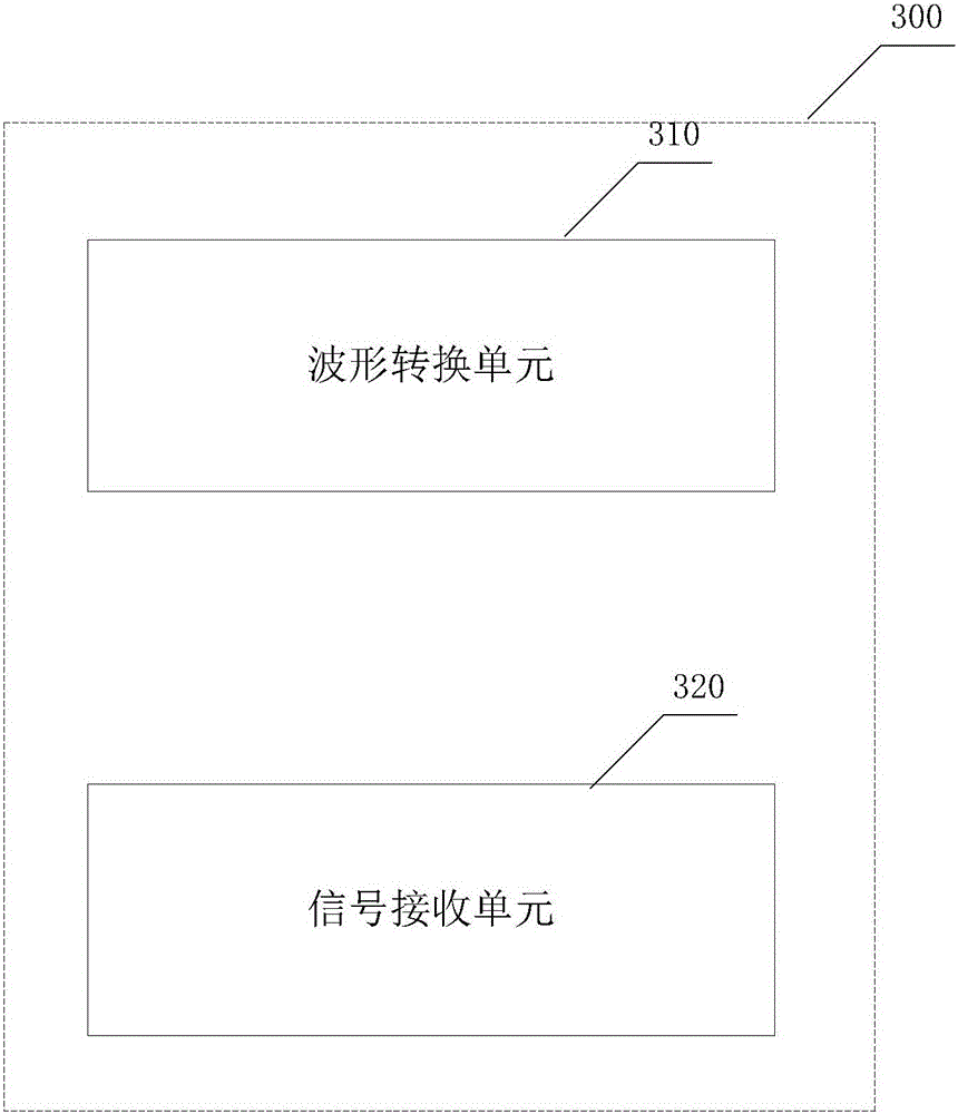
The application discloses a magnetic resonance spectrometer and an apparatus for controlling a magnetic resonance spectrometer based on FPGA. The apparatus includes a control unit and a conversion receiving unit. The control unit includes a clock source. The apparatus is provided with a waveform generation unit and a signal receiving unit therein which are synchronized through the same clock source. The apparatus includes two working modes: a continuous wave mode and an impulse wave mode. The apparatus can output a microwave signal which is modulated by any wave and has higher synchronism and time resolution compared with prior art apparatuses for controlling an electron paramagnetic resonance spectrometer which adopt a plurality of separate clock sources, which enables a second microwave signal in a pulse form generated by the electron paramagnetic resonance spectrometer that is under the control of the apparatus to have a small minimum resolution time of a pulse width and a pulse relative time delay, i.e. a higher time resolution of the second microwave signal. The apparatus is designed based on FPGA, has a higher integration level, and flexible design and low cost.

Description

technical field [0001] The invention relates to the field of magnetic resonance and the technical field of automatic control, more specifically, to a magnetic resonance spectrometer and a control device for the magnetic resonance spectrometer based on FPGA. Background technique [0002] Electron Paramagnetic Resonance (EPR) technology is a spectroscopic method to detect the characteristics of unpaired electrons in samples, and is widely used in the fields of chemistry, physics, materials, environment, life science and medicine. The working mode of the electron paramagnetic resonance spectrometer used in the paramagnetic resonance experiment is mainly divided into pulse wave mode and continuous wave mode. [0003] Electron paramagnetic resonance technology usually uses continuous-wave or pulse-wave microwave signals to excite electron spins, and finally uses electronic readout methods to measure the quantum state of electron spins. Microwave signals are mainly generated by a...

Claims


Application Information

Patent Timeline
IPC IPC(8): G01R33/32
CPCG01R33/32
Inventor 荣星石致富秦熙谢一进王淋蒋振杜江峰
Owner UNIV OF SCI & TECH OF CHINA
Learn More