Water storage power generation system using seabed pressure energy

A power generation system and pressure energy technology, applied in the direction of mechanical power generation mechanism, engine components, machine/engine, etc., can solve the problems of huge investment, small applicability, and large dependence on fresh water resources, and achieve the goal of overcoming the difficulty of site selection and broad The effect of applying the foreground

Inactive Publication Date: 2016-09-07
INST OF ENGINEERING THERMOPHYSICS - CHINESE ACAD OF SCI
View PDF6 Cites 11 Cited by
  • Summary
  • Abstract
  • Description
  • Claims
  • Application Information

AI Technical Summary

Problems solved by technology

However, the traditional pumped storage system needs special geographical conditions to build two storage tanks, the initial investment is huge, and the construction period is long (generally about 5-15 years).
In addition, the traditional pumped storage system uses fresh water as the operating fluid, and the system relies heavily on fresh water resources, which is less applicable to some island countries and cities where fresh water resources are scarce.

Method used


Image

  • Water storage power generation system using seabed pressure energy
  • Water storage power generation system using seabed pressure energy

Examples


specific Embodiment 1

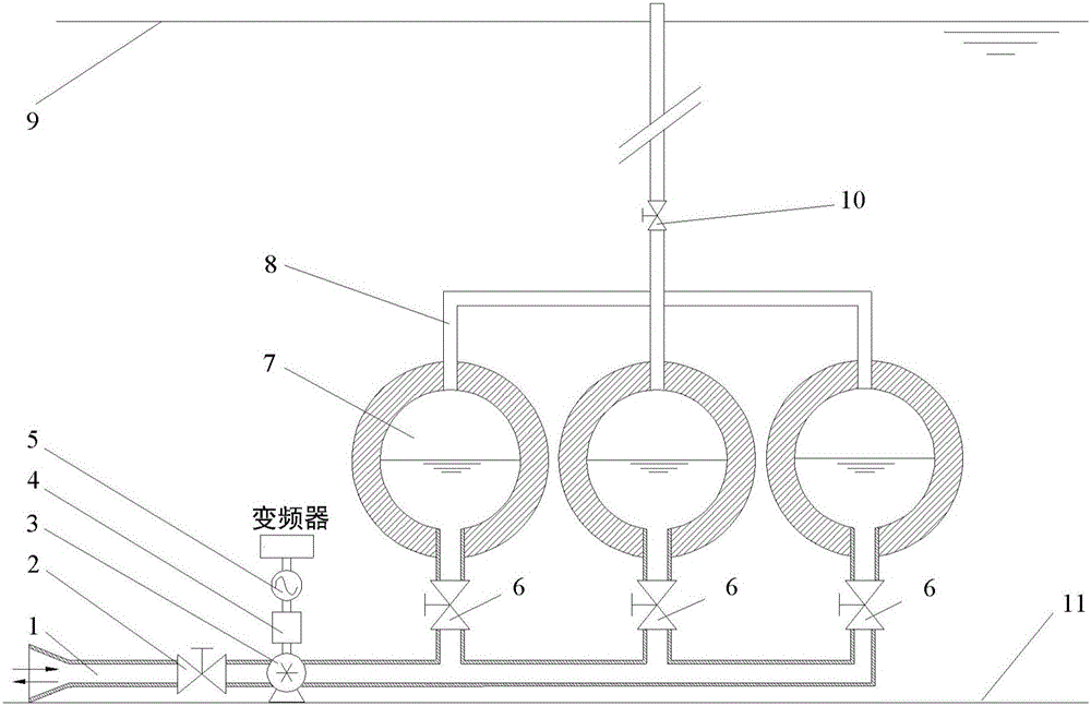
[0048] figure 1 It is a structural schematic diagram of Embodiment 1 of the present invention. Wherein, the pressure regulating valve 10 is opened, the whole system is placed on the seabed 11, and the ventilation pipeline 8 leads to the atmosphere above the sea level 9 . The storage container 7 is fixed on the seabed 11 , one end of which is connected to the seawater pumped storage unit 4 through the valve 6 and the pressure pipe 1 , and the other end is connected to the ventilation pipe 8 . The seawater pumped-storage unit 4 includes a reversible pump-turbine 3, a reversible motor-generator 5 and a variable speed adjustment system, and the reversible pump-turbine 3 is fixedly connected to the transmission shaft of the reversible motor-generator 5.

[0049] When the water storage power generation system utilizing seabed pressure energy of the present invention is storing energy, the pressure pipeline inlet valve 2 and the valve 6 are opened, and the reversible water pump turb...

specific Embodiment 2

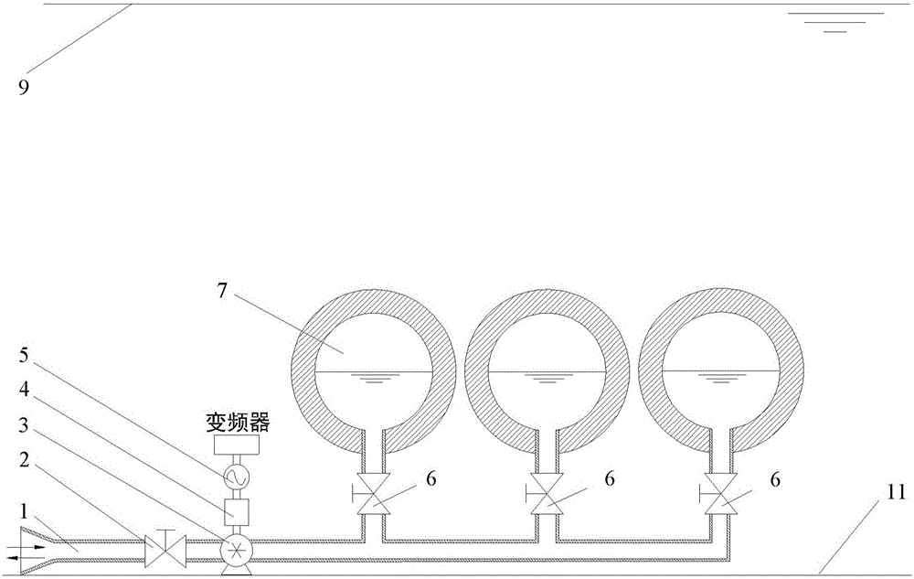
[0052] figure 2 It is a structural schematic diagram of Embodiment 2 of the present invention. Wherein, the pressure regulating valve 10 is closed, the whole system is placed on the seabed 11, the storage container 7 is fixed on the seabed 11, and one end thereof is connected to the seawater pumped storage unit 4 through the valve 6 and the pressure pipe 1. The seawater pumped-storage unit 4 includes a reversible pump-turbine 3 and a reversible motor-generator 5 , and the transmission shaft of the reversible pump-turbine 3 and the reversible motor-generator 5 is fixedly connected. Compared with Example 1, the air pressure in the storage container in Example 2 is lower than atmospheric pressure.

[0053] When the water storage power generation system utilizing seabed pressure energy of the present invention is storing energy, the pressure pipeline inlet valve 2 and the valve 6 are opened, and the reversible water pump turbine 3 in the seawater pumped storage unit 4 is electri...


PUM


Abstract

The invention discloses a water storage power generation system using seabed pressure energy. The power generation system comprises a storage container, a seawater pumping energy accumulation unit and a pressure pipe; the storage container is arranged on a seabed, and includes a first opening end; the first opening end is connected to the pressure pipe; a valve is arranged on the pressure pipe; and the seawater pumping energy accumulation unit is arranged on the seabed, is connected to the pressure pipe, and includes fluid machinery connected with the pressure pipe and a motor/generator in transmission connection with the fluid machinery. The power generation system realizes electric energy storage by using a pressure difference in the seabed and the storage container without constructing high and low impounding reservoirs and being limited by geographical conditions; and the system uses seawater as a working medium for solving the dependency problem of traditional water pumping energy accumulation on fresh water resources. The system is suitable for power supplies with various types, environment-friendly and broad in application prospect.

Description

technical field [0001] The invention belongs to the technical field of electric power storage, in particular to a water storage and power generation system utilizing seabed pressure energy. Background technique [0002] Electric energy storage refers to the process of storing excess electricity through media or equipment and releasing it when needed. In recent years, in order to meet the needs of large-scale development and utilization of new energy such as wind power and photovoltaic power generation and renewable energy; the need to improve the comprehensive utilization efficiency of conventional power systems and energy systems; the need to ensure the security of power and energy supply, power energy storage technology Competing to emerge and develop rapidly. [0003] According to the form of energy conversion, electric energy storage technology can be generally divided into physical energy storage, chemical energy storage and electromagnetic energy storage. Physical en...

Claims


Application Information

Patent Timeline
Patent Type & Authority Applications(China)
IPC IPC(8): F03B13/00F03G7/04
CPCF03B13/00F03G7/04F05B2240/97F03B13/06
Inventor 周学志徐玉杰谭雅倩陈海生
Owner INST OF ENGINEERING THERMOPHYSICS - CHINESE ACAD OF SCI
Why Eureka
Try Eureka