An intelligent rudder with self-calibration function and its working method
A rudder and function technology, applied in the field of intelligent rudder, can solve the problems of increasing the running time, the ship deviates from the course, and loses direction, and achieves the effect of improving accuracy, improving safety and reliability, and simple operation.
- Summary
- Abstract
- Description
- Claims
- Application Information
AI Technical Summary
Problems solved by technology
Method used
Image
Examples
Embodiment 1
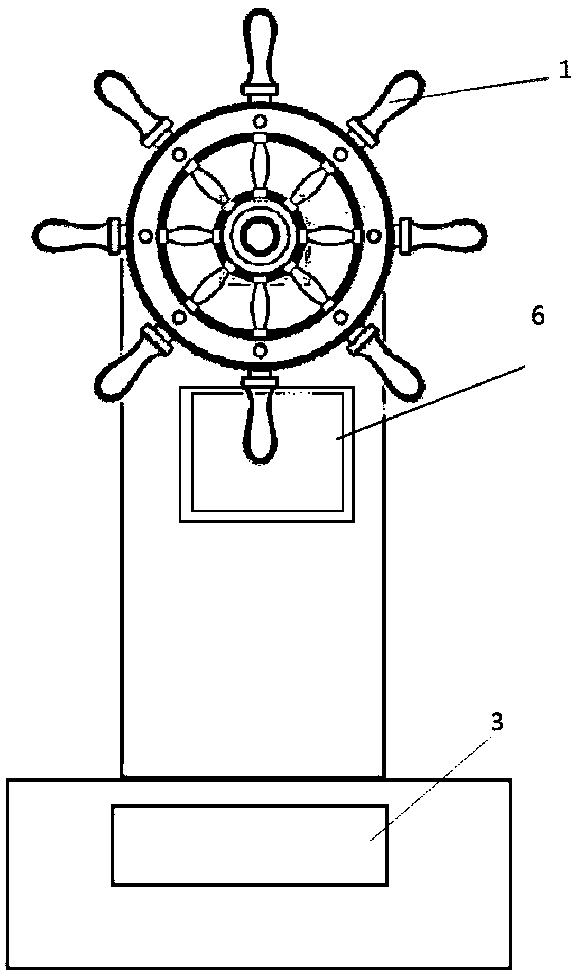
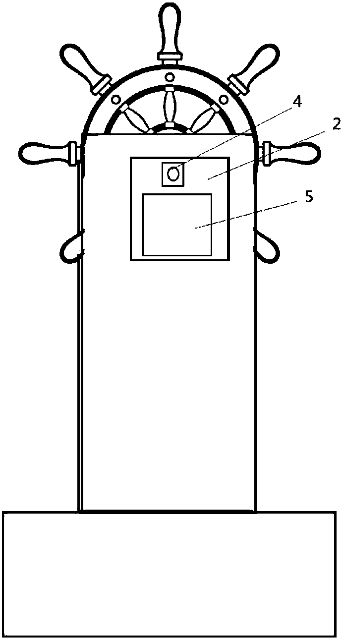
[0029] A kind of intelligent rudder with self-calibration function as shown in the figure includes: rudder body 1, detection device 2 and control device 3, wherein, the described rudder body 1 is provided with an alarm, and the The control device is provided with a calibration module, the detection device 2 is provided with a wind speed and direction sensor 4, a water flow sensor, and a travel recorder 5, and the rudder body 1 is provided with a base, a column, a rudder stock, a main Rudders, protective shells and forks.
[0030] The relationship between the above components is as follows:
[0031] The wind speed and direction sensor 4 is located on the top of the rudder body 1, the water flow sensor is located below the hull, and it is connected with the rudder body 1, and the travel recorder 5 is located on the rudder body 1 , the control device 3 is located inside the rudder body 1, and the wind speed and direction sensor 4, the water flow sensor and the travel recorder 5 ...
Embodiment 2
[0038] The structure of the rudder in the working method of an intelligent rudder with a self-calibration function described in this embodiment is the same as that of Embodiment 1.
[0039]A kind of intelligent rudder with self-calibration function as shown in the figure includes: rudder body 1, detection device 2 and control device 3, wherein, the described rudder body 1 is provided with an alarm, and the The detection device 2 is provided with a wind speed and direction sensor 4, a water flow sensor, and a trip recorder 5. The control device 3 is provided with a calibration mechanism, and the rudder body 1 is provided with a base, a column, a rudder stock, Main rudder, protective shell and forks.
[0040] The relationship between the above components is as follows:
[0041] The wind speed and direction sensor 4 is located on the top of the rudder body 1, the water flow sensor is located below the hull, and it is connected with the rudder body 1, and the travel recorder 5 is...
PUM
 Abstract
Description
Claims
Application Information
 - R&D
- Intellectual Property
- Life Sciences
- Materials
- Tech Scout
- Unparalleled Data Quality
- Higher Quality Content
- 60% Fewer Hallucinations
Browse by: Latest US Patents, China's latest patents, Technical Efficacy Thesaurus, Application Domain, Technology Topic, Popular Technical Reports.
© 2025 PatSnap. All rights reserved.Legal|Privacy policy|Modern Slavery Act Transparency Statement|Sitemap|About US| Contact US: help@patsnap.com


