


Quick Research
Generate reliable direction feasibility study reports for your R&D in just a few steps.

Technical Q&A
Discover and master advanced knowledge NOW. Basics, ideas, possibilities, all at once.

Find Solutions
As an expert in R&D theories, this can generate solutions to your technical problems instantly.

Evaluate Feasibility
Analyze your overall solution with one click, know your potential R&D risks in advance.

Monitor Landscape
Get weekly tech updates, stay abreast of the latest tech innovations and key insights.
Remote control power supply protection box used for irrigation
A power protection and remote control technology, applied in the field of protection devices and remote control power protection boxes, can solve problems such as affecting the normal operation of the equipment, increasing the temperature in the box, and burning out the equipment in the box, and achieving a reliable design principle and simple structure. , to avoid the effect of lightning strikes
- Summary
- Abstract
- Description
- Claims
- Application Information
AI Technical Summary
Problems solved by technology
Method used
Image

Examples
Embodiment 1
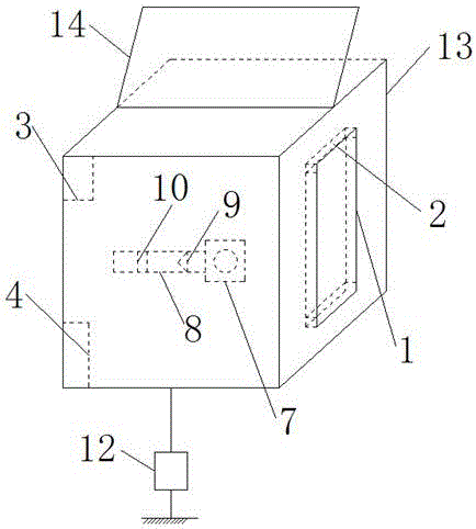
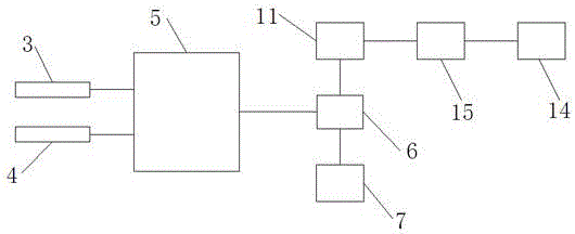
[0058] Such as figure 1 and 2 As shown, a remote control power supply protection box for watering provided by the present invention includes a box body 12 on which a movable door 1 is arranged; a rubber sealing ring 2 is arranged on the inner periphery of the movable door 1; A temperature sensor 3 and a humidity sensor 4 are installed in the box body 12, and the temperature sensor 3 and the humidity sensor 4 are all connected to a microcontroller 5, and the output end of the microcontroller 5 is connected to an electromagnetic relay 6;
[0059] A drainage fan 6 is also installed in the box body 13, and the drainage fan 6 is connected to the outside world through a drainage duct 8. A one-way valve 9 and a silica gel layer 10 are sequentially arranged in the drainage duct 8 along the drainage wind direction, The draft fan 7 is connected to the power supply 11 through the electromagnetic relay 6;
[0060] The bottom of the box body 13 is also connected to the ground through a g...
Embodiment 2
[0082] The difference between this embodiment and Embodiment 1 is that the parts by weight of the raw materials of the insulation board are different, specifically:
[0083] The parts by weight of each raw material of the heat insulating board are:
[0084] 13 parts of substrate;
[0085] Asbestos 18 parts;
[0086] 22 parts of aluminum powder;
[0087] 8 parts of binder;
[0088] 37 parts of zirconium dioxide;
[0089] Foaming agent 13 parts.
Embodiment 3
[0091] The difference between this embodiment and Embodiment 1 is that the parts by weight of the raw materials of the insulation board are different, specifically:
[0092] The parts by weight of each raw material of the heat insulating board are:
[0093] 14 parts of substrate;
[0094] Asbestos 20 parts;
[0095] 24 parts of aluminum powder;
[0096] 9 parts of binder;
[0097] 40 parts of zirconium dioxide;
[0098] Foaming agent 15 parts.
PUM
 Abstract
Description
Claims
Application Information
 - R&D Engineer
- R&D Manager
- IP Professional
- Industry Leading Data Capabilities
- Powerful AI technology
- Patent DNA Extraction
Browse by: Latest US Patents, China's latest patents, Technical Efficacy Thesaurus, Application Domain, Technology Topic, Popular Technical Reports.
© 2024 PatSnap. All rights reserved.Legal|Privacy policy|Modern Slavery Act Transparency Statement|Sitemap|About US| Contact US: help@patsnap.com