
Automatic dust removal equipment for electric energy meters

A technology of automatic dust removal and electric energy meter, which is applied in the direction of cleaning methods, cleaning methods and utensils, chemical instruments and methods using gas flow, etc., which can solve problems such as high labor intensity, dust inhalation damage to the body, low production efficiency, etc.

Active Publication Date: 2016-08-31
NINGBO SANXING MEDICAL & ELECTRIC CO LTD
View PDF6 Cites 17 Cited by
  • Summary
  • Abstract
  • Description
  • Claims
  • Application Information

AI Technical Summary

Problems solved by technology

The traditional dust removal method relies on manually using an air gun to clean the inside of the electric energy meter. On the one hand, this dust removal method will cause the cleaners to inhale the dust into the body and cause harm. On the other hand, it is labor-intensive and the production efficiency is low.
Although some automatic dust removal equipment for electric energy meters have also appeared at present, such as the Chinese invention patent application whose application publication number is CN103691702, the automatic dust removal equipment for this electric energy meter does not separate the conveying device and the dust removal device, so that the dust blown out by the dust removal device It is easy to blow back into the electric energy meter, and because the bottom case of the electric energy meter is always open during transportation, it is difficult for the dust in the bottom case to be completely blown out by the dust removal device, and the dust removal effect is not ideal

Method used


Image

  • Automatic dust removal equipment for electric energy meters
  • Automatic dust removal equipment for electric energy meters
  • Automatic dust removal equipment for electric energy meters

Examples


Embodiment

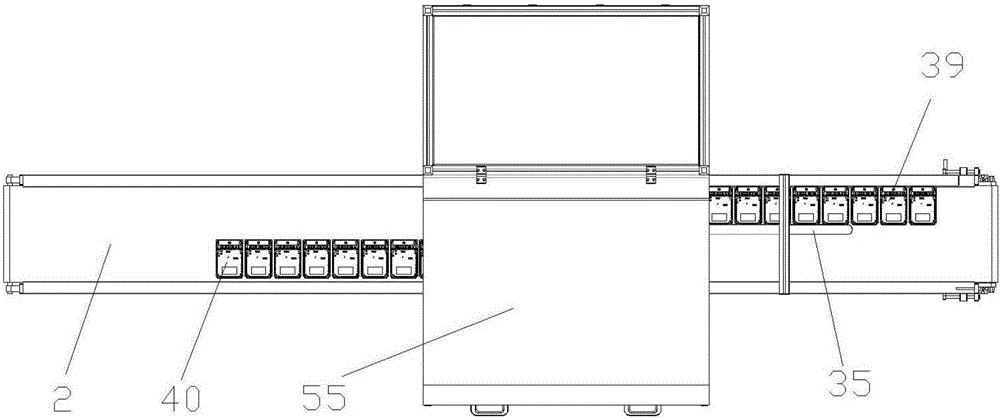
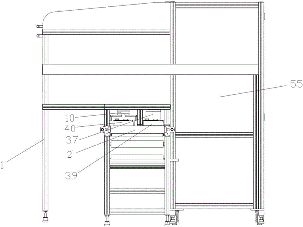
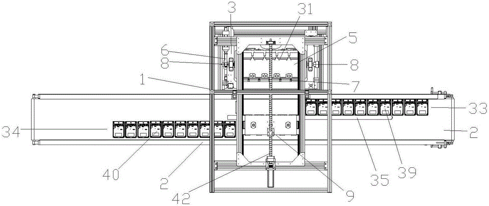
[0026] Such as Figure 1 to Figure 7 , an automatic dedusting device for an electric energy meter, comprising a frame 1, a conveying device 2 and a dedusting device 3, characterized in that: the conveying device 2 and the dedusting device 3 are arranged side by side at the front and rear of the frame 1, side by side Setting means that the conveying device 2 and the dust removal device 3 are almost on the same level, and the dust removal device 3 includes a positioning tool 5 for fixing a plurality of electric energy meters, a blowing device 7 and a turning mechanism 6 for driving the positioning tool 5 to turn up and down , the top of the frame 1 is located between the conveying device 2 and the positioning tool 5 and is also provided with a transfer mechanism 9, which is used to grab the electric energy meter 39 to be dedusted on the conveying device 2 and move it to the positioning tool 5 or grasp it. Get the dust-removed electric energy meter 40 on the positioning tool 5 an...


PUM


Abstract

The invention discloses automatic dust removal equipment for electric energy meters. The automatic dust removal equipment for the electric energy meters comprises a rack, a conveying device and a dust removal device. The automatic dust removal equipment is characterized in that the conveying device and the dust removal device are arranged on the front part and the rear part of the rack in parallel; the dust removal device comprises a location fixture used for fixing the plurality of electric energy meters, an air-blowing device and a turnover mechanism used for driving the location fixture to turn over up and down; and a transferring-loading mechanism is further arranged above the rack, and between the conveying device and the location fixture, and used for grabbing the electric energy meters to be subjected to dust removal on the conveying device and moving the electric energy meters onto the location fixture or grabbing the electric energy meters subjected to dust removal on the location fixture and moving the electric energy meters onto the conveying device. According to the automatic dust removal equipment for the electric energy meters, the conveying device and the dust removal device are mutually separated, so that dust in the electric energy meters can be adequately eliminated.

Description

technical field [0001] The invention relates to the technical field of automatic dust removal, in particular to an automatic dust removal device for an electric energy meter. Background technique [0002] In order to ensure the quality of the electric energy meter, it is necessary to remove dust before the electric energy meter is packaged and leaves the factory, that is, to remove dust inside the electric energy meter when the upper cover and the bottom case of the electric energy meter are separated. The traditional dust removal method relies on manually using an air gun to clean the inside of the electric energy meter. On the one hand, this dust removal method will cause the cleaners to inhale dust into the body and cause harm. On the other hand, it is labor-intensive and low in production efficiency. Although some automatic dust removal equipment for electric energy meters have also appeared at present, such as the Chinese invention patent application whose application p...

Claims


Application Information

Patent Timeline
IPC IPC(8): B08B5/02B08B7/02B08B13/00
CPCB08B5/02B08B7/02B08B13/00
Inventor 郑坚江张峰峰张欢梁文晖
Owner NINGBO SANXING MEDICAL & ELECTRIC CO LTD
Learn More