Method and device for determining the polarity of rotor poles, variable frequency machines and electric rotating machines

A technology for rotating electrical machines and rotors, applied in the field of rotating electrical machines and synchronous motors, which can solve problems such as failure to provide results, low energy density magnet demagnetization, and insufficient reliability, and achieve the effect of reducing the risk of undesired rotation

Active Publication Date: 2020-11-27
MOTEURS LEROY SOMER
View PDF11 Cites 0 Cited by
  • Summary
  • Abstract
  • Description
  • Claims
  • Application Information

AI Technical Summary

Problems solved by technology

However, this is only the case if the rotor-generated flux through the magnetic circuit of the stator is sufficiently significant, i.e. the rotor has a high flux concentration or the magnets have a high The case of energy density
[0013] In contrast, this approach is useful when applied to synchronous reluctance machines that include permanent magnets at the rotor, and more particularly when these permanent magnets have a low energy density (e.g., these permanent magnets are magnets made of ferrite ), this method does not give good results
In fact, in the case of synchronous reluctance motors and using rotors with permanent magnets of low energy density, the no-load flux may be too low for the obtained results to be reliable enough and may lead to high error rates
Also, to remedy this problem, large current changes are attempted, however, this may cause a high risk of demagnetization of low energy density magnets

Method used


Image

  • Method and device for determining the polarity of rotor poles, variable frequency machines and electric rotating machines
  • Method and device for determining the polarity of rotor poles, variable frequency machines and electric rotating machines
  • Method and device for determining the polarity of rotor poles, variable frequency machines and electric rotating machines

Examples


Embodiment Construction

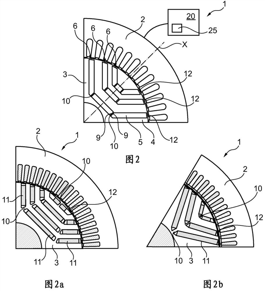
[0097] figure 1 There is shown a rotating electric machine 1 comprising a stator 2 and a flux concentrating rotor 3 having a magnetic rotor block 4 in which seats 5 are formed to define poles of the rotor, each pole having a radial axis X.

[0098] In this example, the rotor comprises nine seats 5 per pole arranged in 3 concentric rows 6 around each pole, the concavities of the rows facing the air gap. Row 6 comprises three seats 5 arranged successively in a row. The three rows 6 of the same pole are of decreasing length in the direction of the air gap, the longest on the axis of rotation and the shortest on the air gap side.

[0099] Seat 5 is in an elongated form. The seats 5 each comprise 2 short sides 9 , between which the respective short sides 9 of two consecutive seats 5 in the same row 6 define a material bridge 10 . The material bridges 10 generally extend along a longitudinal axis Z of the bridges, which is oriented so as to approach the radial axis X of the corr...


PUM


Abstract

The invention relates to a method for determining the polarity of the poles of a rotor (3) of a rotating electrical machine (1) having an estimated position relative to the stator, said method comprising the steps of: a) applying an excitation voltage to said the stator to successively generate two different magnetic fluxes within the saturable magnetic region of said pole, one flux coincident with and the other flux opposite to that of the magnet, so as to cause the magnetic flux to at least one of said fluxes saturating the saturable magnetic region; and b) determining the polarity of the magnetic poles based on a difference in time evolution of currents generated in the stator by the two magnetic fluxes.

Description

technical field [0001] The present invention relates to a rotating electrical machine, and in particular to a rotating electrical machine comprising a rotor with permanent magnets. [0002] The object of the invention is to determine the position of at least one pole of a rotor with permanent magnets in a stationary state and without using conventional position sensors. [0003] The invention relates more particularly to a method for determining the position of at least one magnetic pole of a rotor with permanent magnets, and also to a device for determining the position of a magnetic pole. [0004] The invention applies generally to synchronous machines comprising a rotor with permanent magnets, and preferably to synchronous reluctance machines with permanent magnets or to machines with a flux concentrated rotor. Background technique [0005] The control of a synchronous machine with permanent magnets is based on knowing the position of the rotor, and in particular the pos...

Claims


Application Information

Patent Timeline
IPC IPC(8): H02P21/18H02P21/22H02P21/32H02P6/18H02P25/026
CPCH02K1/27H02P6/18H02K1/2766H02P6/182H02K21/14H02P6/183
Inventor 沙维尔·雅诺雅克·圣-米歇尔马蒂亚斯·蒂恩切夫-亚麻德
Owner MOTEURS LEROY SOMER
Why Eureka
Try Eureka