Tire anti-skid device and main body for tire anti-skid device
An anti-skid device and tire technology, applied in anti-skid devices, tire parts, transportation and packaging, etc., can solve the problems of high cost, heavy physical labor, and high fuel consumption of snow tires, and achieve low manufacturing costs and simple main body Effect
- Summary
- Abstract
- Description
- Claims
- Application Information
AI Technical Summary
Problems solved by technology
Method used
Image
Examples
no. 1 example
[0080] "summary"
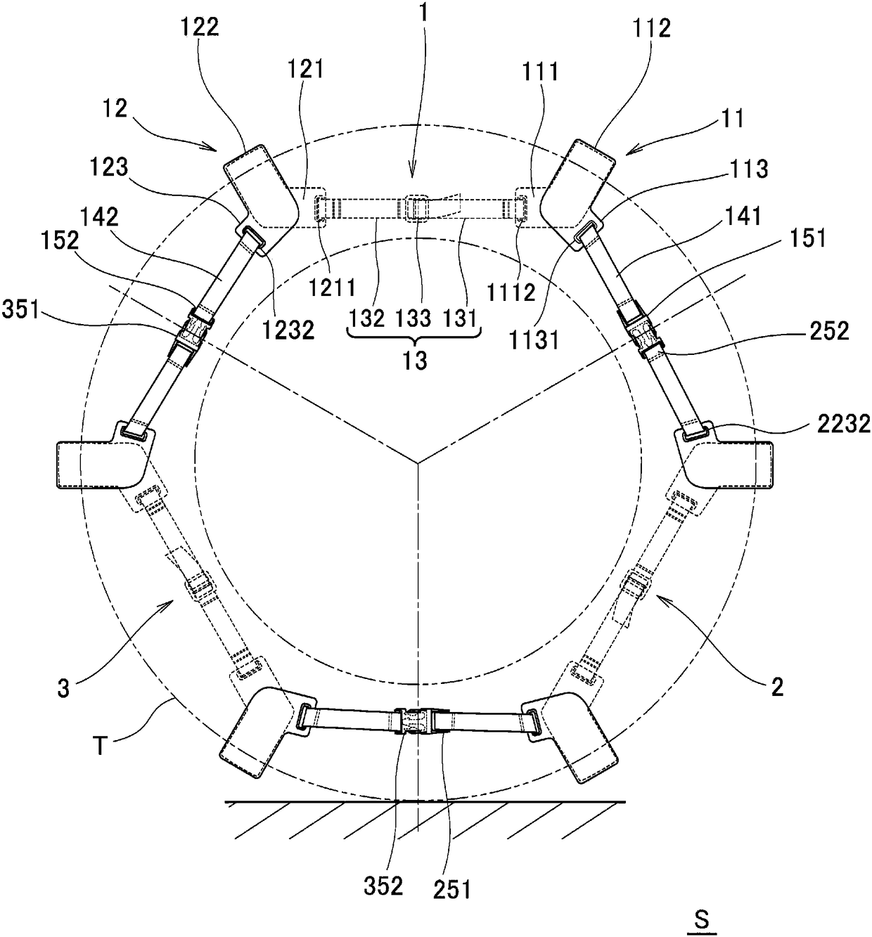
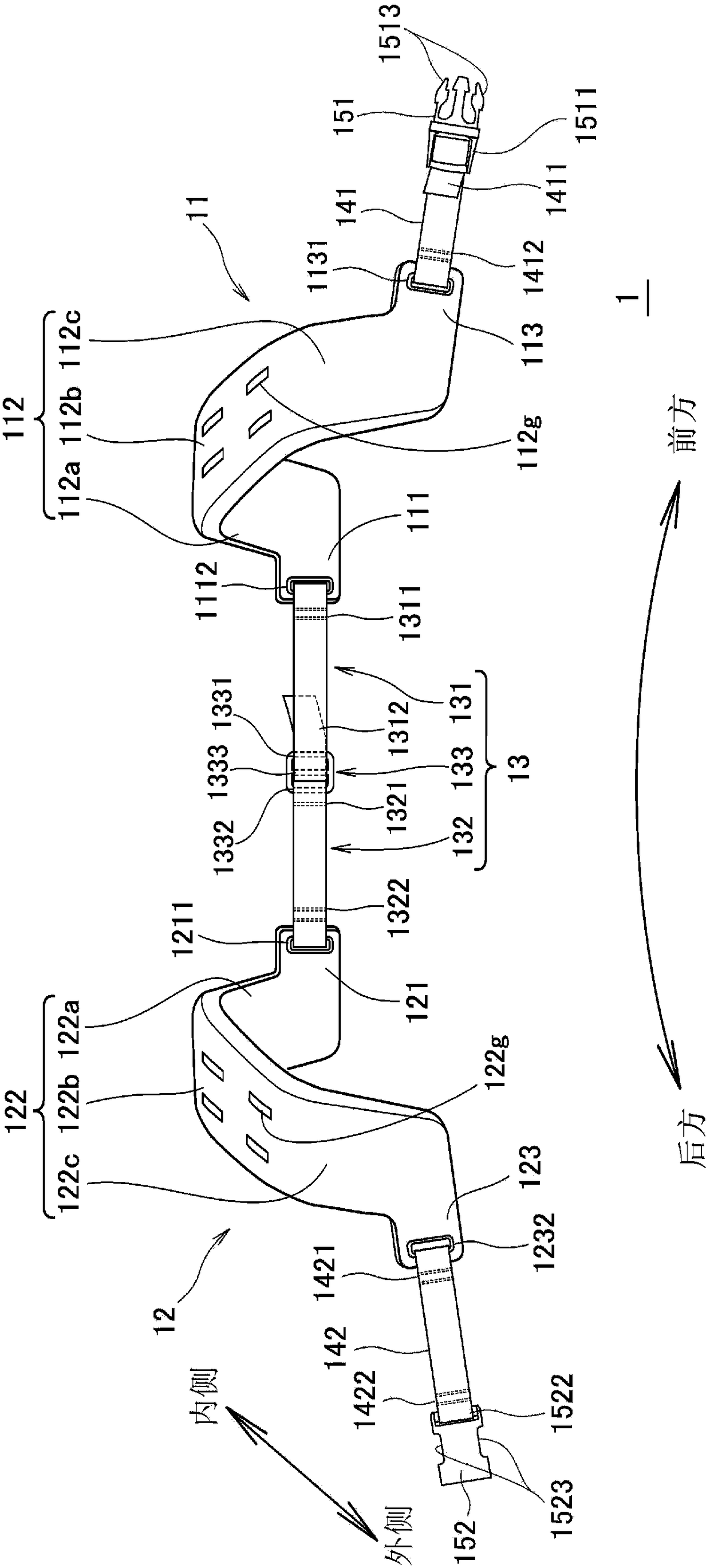
[0081] exist figure 1 A tire anti-skid device S (only referred to as "anti-skid device S") as an embodiment of the present invention is shown in a case where it is mounted on a tire T for a large vehicle. The anti-slip device S is composed of three unit units 1 , 2 , and 3 . The unit units 1, 2, and 3 have the same form respectively, and they are located on the decorative surface side of the wheel (not shown), that is, outside the tire T ( figure 1 The front side of the paper) are connected together in a detachable manner. Hereinafter, for the unit cell 1 as one of them, refer to figure 2 and as its partial enlargement image 3It will be described in detail, and descriptions related to other unit cells will be omitted. In addition, the same reference numerals are attached to the same components, and their detailed descriptions are appropriately omitted.
[0082] "Unit Unit"
[0083] The unit unit 1 is composed of a first main body 11, a second main ...
no. 2 example
[0106] exist Figure 4 The unit unit 5 is shown in FIG. It is formed by the inner belt-shaped connecting body 53 . In addition, the same reference numerals are assigned to the same components as in the case of the unit cell 1, and detailed descriptions are omitted. In addition, parts not described in detail are basically the same as in the case of the first embodiment. The above-mentioned situation is also the same in the following examples.
[0107] The first main body 51 and the second main body 52 of the unit unit 5 are composed of the unified main body 50 of the same form. Therefore, in the unit unit 5, there is no need to prepare two kinds of main bodies, and one kind of main body can be used in combination. Therefore, compared with the case of the unit unit 1 (2, 3), it is possible to realize manufacturing by reducing the number of parts. Cost and management cost reduction.
[0108]Specifically, the integrated main body 50 has a U-shaped portion 502 and four extendi...
no. 3 example
[0113] exist Figure 5 A unit unit 7 is shown in , which is obtained by replacing the first body 11 of the unit unit 1 with a first body 71 and replacing the second body 12 with a second body 27 .
[0114] Both the first body 71 and the second body 72 of the unit unit 7 are constituted by the unified body 70 . This unified body 70 is formed in a simpler shape than the aforementioned unified body 50 . If the unit unit 7 composed of the integrated body 70 is used, not only the reduction of manufacturing cost and management cost can be further realized compared with the case of using the unit unit 1 (2, 3), but also compared with the case of using the unit unit 5 It is also possible to further reduce manufacturing costs and management costs.
[0115] Specifically, the integrated main body 70 is composed of an inner side part 701 which doubles as an inner extension part (an inner front extension part and an inner rear extension part), a cross part 702 which becomes a ground cont...
PUM
 Abstract
Description
Claims
Application Information
 - R&D
- Intellectual Property
- Life Sciences
- Materials
- Tech Scout
- Unparalleled Data Quality
- Higher Quality Content
- 60% Fewer Hallucinations
Browse by: Latest US Patents, China's latest patents, Technical Efficacy Thesaurus, Application Domain, Technology Topic, Popular Technical Reports.
© 2025 PatSnap. All rights reserved.Legal|Privacy policy|Modern Slavery Act Transparency Statement|Sitemap|About US| Contact US: help@patsnap.com


