Floating carrier

A carrier and overall technology, applied in the field of mechanical parts, can solve the problems of poor light transmission and air permeability of water bodies, unfavorable application of solar modules, unfavorable transportation and installation, etc., and achieve high environmental friendliness, enhanced anti-destructive performance, and simple structure Effect

Inactive Publication Date: 2016-08-24
HANERGY CO INNO MOBILE ENERGY INVESTMENT CO LTD
View PDF6 Cites 0 Cited by
  • Summary
  • Abstract
  • Description
  • Claims
  • Application Information

AI Technical Summary

Problems solved by technology

[0004] However, due to the flexible characteristics of the water surface, it is difficult to apply the solar power generation system on the water surface.
In recent years, the research and development work on the carrier of the solar power generation system applied on the water surface is gradually carried out. At present, the most common one is to carry it in the form of a whole piece of floating body or in the form of a float, but these carriers have Their respective problems lie, such as: the whole piece of floating body uses a lot of materials, which causes problems such as high cost, heavy weight, unfavorable transportation and installation, and because the whole piece of floating body covers a large area of ​​the water surface, resulting in water body The light transmission and air permeability are very poor, and it has a great impact on the ecological environment in the water area. In addition, the size of the whole floating body is fixed and cannot be adjusted, which is not conducive to the application of solar modules of various sizes; Concerns about stability

Method used


Image

  • Floating carrier
  • Floating carrier
  • Floating carrier

Examples


Embodiment 1

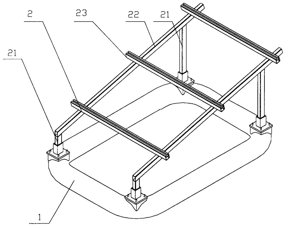
[0028] Such as figure 1 The floating carrier shown includes a floating piece 1 and a mounting bracket 2 that are fixed to each other. The floating piece 1 is a frame structure, wherein the floating piece 1 is an integrally formed rectangular frame structure, and the floating piece 1 and the mounting bracket 2 are made of FRP in non-metal-non-metal composite materials. In order to meet the installation needs of solar cells, the angle between the installation surface of the installation bracket 2 and the horizontal plane is 15°, and the installation bracket 2 specifically includes four uprights 21 fixedly connected to the four corners of the floating member 1 , and the columns 21 are divided into two groups of different heights, wherein the two heights at the diagonal positions are different; the tops of the two adjacent columns 21 with different heights are connected by a support beam 22, and the two parallel columns Three position-adjustable installation beams 23 are arranged...

Embodiment 2

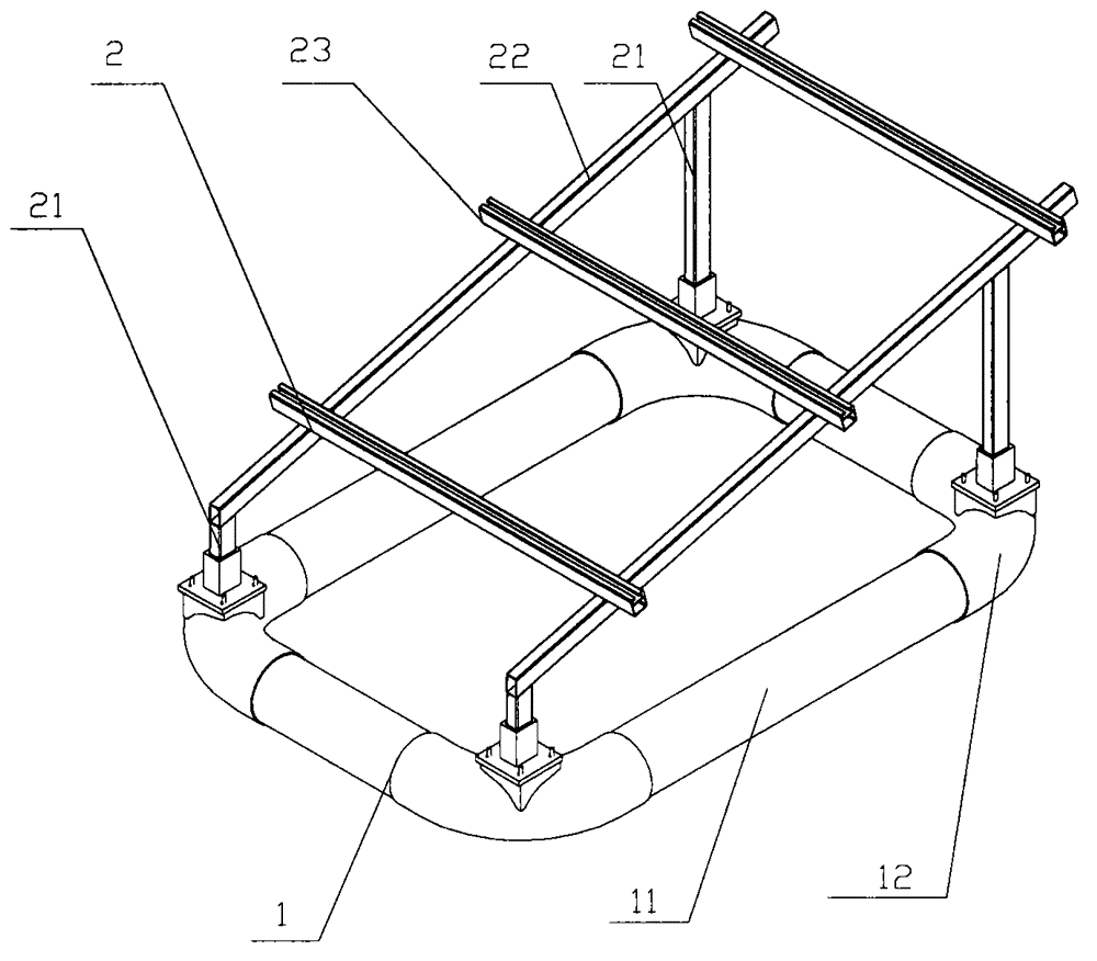
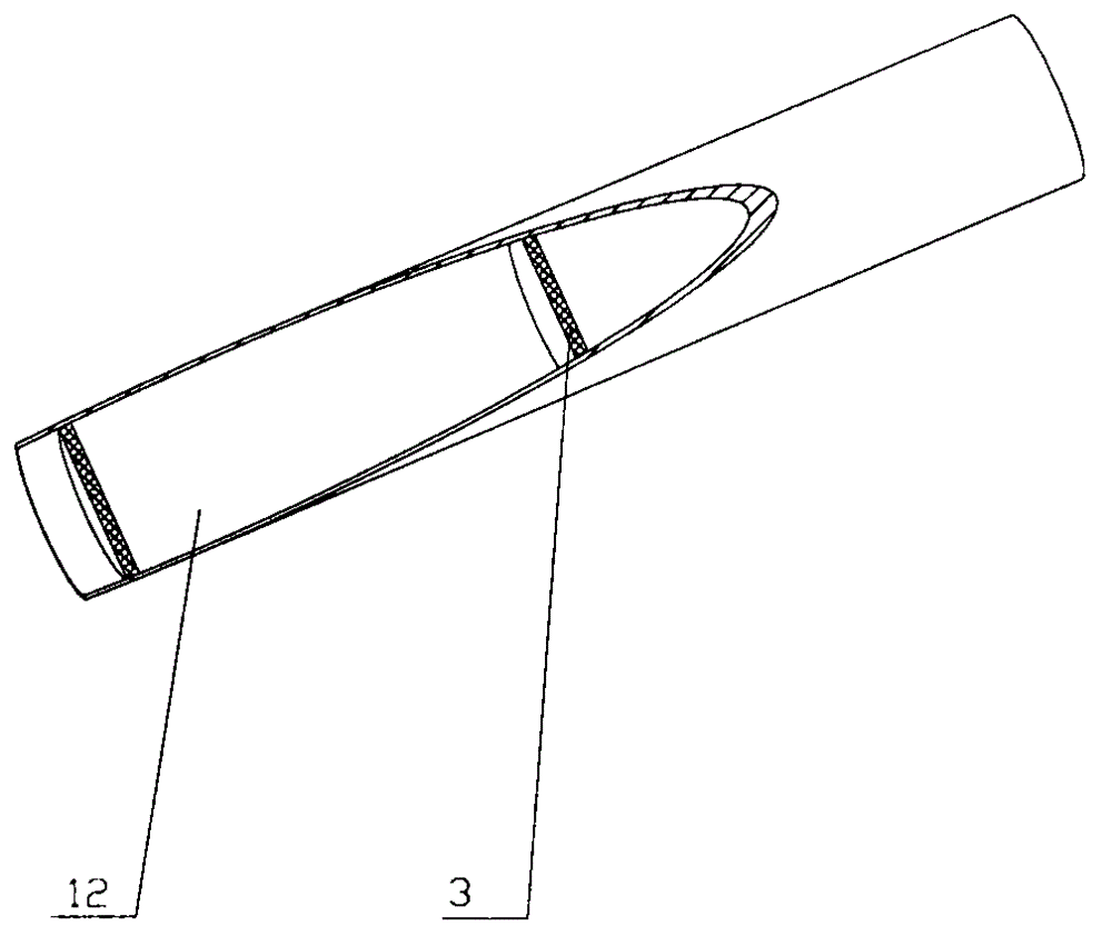
[0030] Such as figure 2 , image 3 The floating carrier shown includes a floating part 1 and a mounting bracket 2 fixedly connected to each other. The floating part 1 is a frame structure, wherein the floating part 1 is a split frame structure with rounded corners, and the material is glass fiber reinforced plastic. Specifically, the floating member 11 of the hollow straight pipe structure and the connecting member 12 of the hollow rounded elbow structure are glued to form an airtight hollow structure, and the floating member 11 of the hollow straight pipe and the hollow rounded elbow structure Baffles 13 are provided in the connecting members 12, so as to separate each of the floating members 11 and the connecting members 12 into a plurality of airtight hollow sections, so as to further enhance the safety performance of the floating carrier. The specific structure of the mounting bracket 2 is the same as the structure and material described in Embodiment 1, except that the ...


PUM


Abstract

The invention relates to a floating carrier. The carrier comprises a floating component and an installation support which are mutually and fixedly connected. The floating component is frame-type structure. In the invention, the floating component of the floating carrier is set to be the frame-type structure; compared to a traditional entire block structure, by using the frame-type structure, material adoption is saved, cost is reduced, weight is mitigated, and installation and transport are convenient. Simultaneously, light transmission and air permeability of an application water area of the floating carrier are increased, an ecological environment of the water area is not influenced, a friendly degree of the environment is increased and a wide application prospect is possessed.

Description

technical field [0001] The invention belongs to the field of mechanical components, and in particular relates to a physical carrier applicable to fluids. Background technique [0002] The solar power generation system is a power generation system that uses solar cells to directly convert solar energy into electrical energy. It is characterized by high reliability, long service life, no pollution to the environment, independent power generation and grid-connected operation, and is favored by enterprises and organizations in various countries. It has broad development prospects. However, due to the low energy density of surface solar energy, the construction of solar power stations is often based on a large area. The use of solar energy has deprived humans of other uses of the land, and humans have turned their attention to the vast water surface with abundant solar energy. [0003] Building solar power plants on water has the following advantages: first, the conversion effi...

Claims


Application Information

Patent Timeline
Patent Type & Authority Applications(China)
IPC IPC(8): H02S20/30B63B35/44
CPCF24S20/70F24S25/12Y02E10/47Y02E10/50
Inventor 张波彭侃王玉晓吴国发
Owner HANERGY CO INNO MOBILE ENERGY INVESTMENT CO LTD
Why Eureka
Try Eureka