Optical imaging system
An optical imaging system and imaging surface technology, applied in optics, optical components, instruments, etc., can solve problems such as inability to meet photography requirements, difficulty in manufacturing, and deterioration of surrounding imaging quality.
- Summary
- Abstract
- Description
- Claims
- Application Information
AI Technical Summary
Problems solved by technology
Method used
Image
Examples
Embodiment approach
[0151] The sum of the focal lengths fp of each lens with positive refractive power in the optical imaging system is ΣPP, and the sum of the focal lengths of each lens with negative refractive power is ΣNP. An embodiment of the optical imaging system of the present invention satisfies the following conditions: <ΣPP≦200; and 0
[0152] The first lens may have positive refractive power, and its object side may be convex. Thus, the positive refractive power of the first lens can be properly adjusted, which helps to shorten the total length of the optical imaging system.
[0153] The second lens may have negative refractive power. Thereby, aberrations generated by th...
no. 1 example
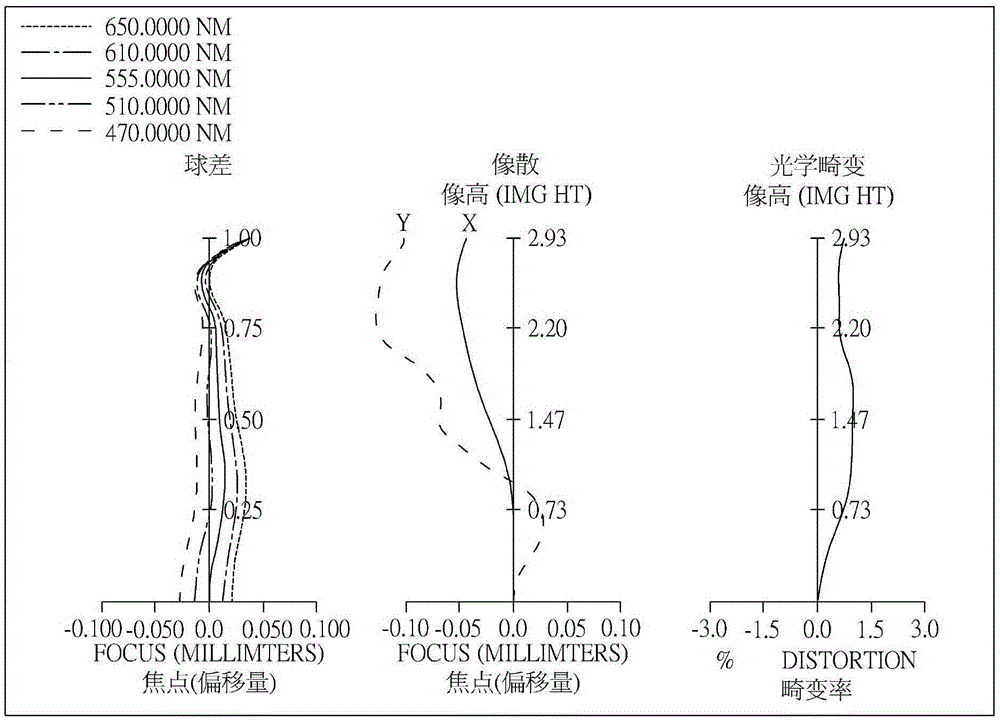
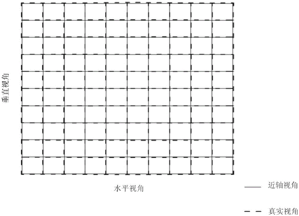
[0188] Please refer to Figure 1A and Figure 1B ,in Figure 1A Representing a schematic diagram of an optical imaging system according to a first embodiment of the present invention, Figure 1B From left to right are the spherical aberration, astigmatism and optical distortion curves of the optical imaging system of the first embodiment. Figure 1C It is a TV distortion curve diagram of the optical imaging system of the first embodiment. Depend on Figure 1A It can be seen that the optical imaging system includes an aperture 1, a first lens 110, a second lens 120, a third lens 130, a fourth lens 140, an infrared filter 170, an imaging surface 180, and an image sensing element in order from the object side to the image side. 190.
[0189] The first lens 110 has positive refractive power and is made of plastic material. The object side 112 is convex, and the image side 114 is concave, both of which are aspherical. Both the object side 112 and the image side 114 have an inflec...
no. 2 example
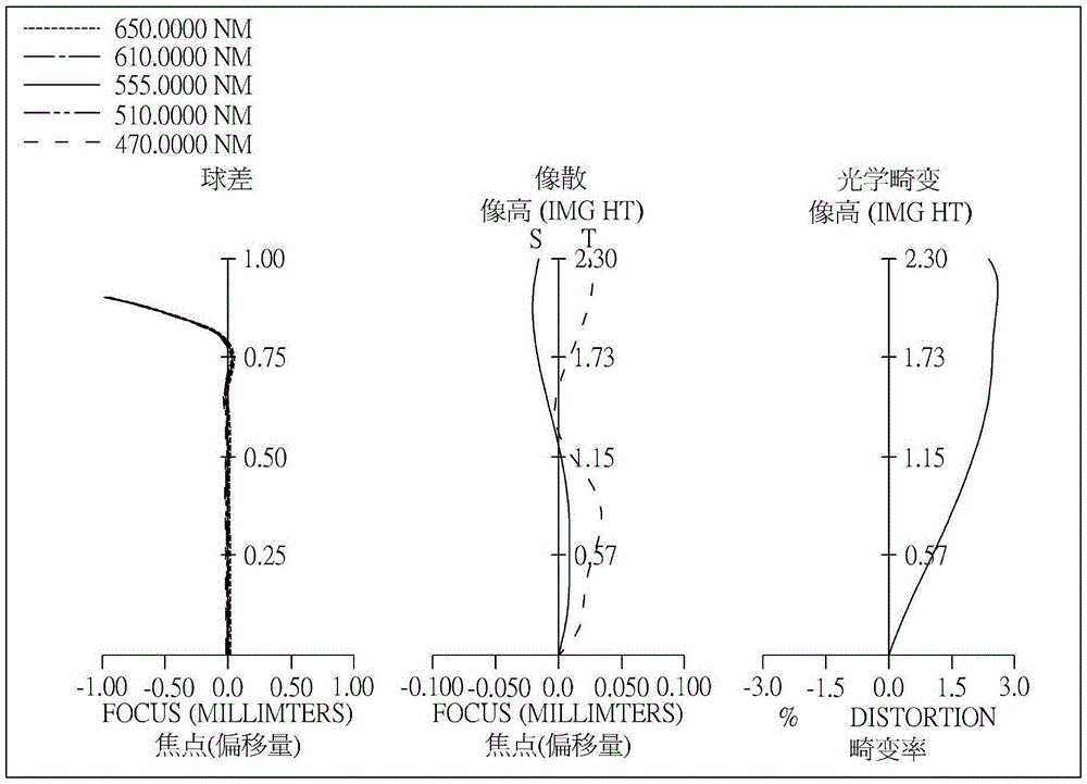
[0240] Please refer to Figure 2A and Figure 2B ,in Figure 2A A schematic diagram showing an optical imaging system according to a second embodiment of the present invention, Figure 2B From left to right are the spherical aberration, astigmatism and optical distortion curves of the optical imaging system of the second embodiment. Figure 2C It is a TV distortion curve diagram of the optical imaging system of the second embodiment. Depend on Figure 2A It can be seen that the optical imaging system sequentially includes a first lens 210, an aperture 200, a second lens 220, a third lens 230, a fourth lens 240, an infrared filter 270, an imaging surface 280, and an image sensing element from the object side to the image side. 290.
[0241] The first lens 210 has positive refractive power and is made of plastic material. The object side 212 is convex, and the image side 214 is convex, both of which are aspherical. The object side 212 has an inflection point.
[0242] The ...
PUM
 Abstract
Description
Claims
Application Information
 - R&D Engineer
- R&D Manager
- IP Professional
- Industry Leading Data Capabilities
- Powerful AI technology
- Patent DNA Extraction
Browse by: Latest US Patents, China's latest patents, Technical Efficacy Thesaurus, Application Domain, Technology Topic, Popular Technical Reports.
© 2024 PatSnap. All rights reserved.Legal|Privacy policy|Modern Slavery Act Transparency Statement|Sitemap|About US| Contact US: help@patsnap.com


