
Multi-section gradually-changing coaxial type component high-voltage fast pulse response test fixture

A technology of impulse response and test fixtures, which is applied in the direction of measuring devices, measuring electrical variables, measuring device casings, etc., can solve the problems of low compressive strength, unsatisfactory high-frequency transmission characteristics, and affecting test results, etc., and achieve high compressive strength value, good promotion and use prospects, and the effect of reducing waveform distortion

Active Publication Date: 2016-08-24
UNIT 61489 OF PLA +1
View PDF8 Cites 3 Cited by
  • Summary
  • Abstract
  • Description
  • Claims
  • Application Information

AI Technical Summary

Problems solved by technology

The purpose of the present invention is to solve the problem of low compressive strength of the test fixture and unsatisfactory high-frequency transmission characteristics in the prior art and test devices, which affect the test results

Method used

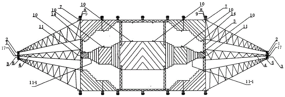
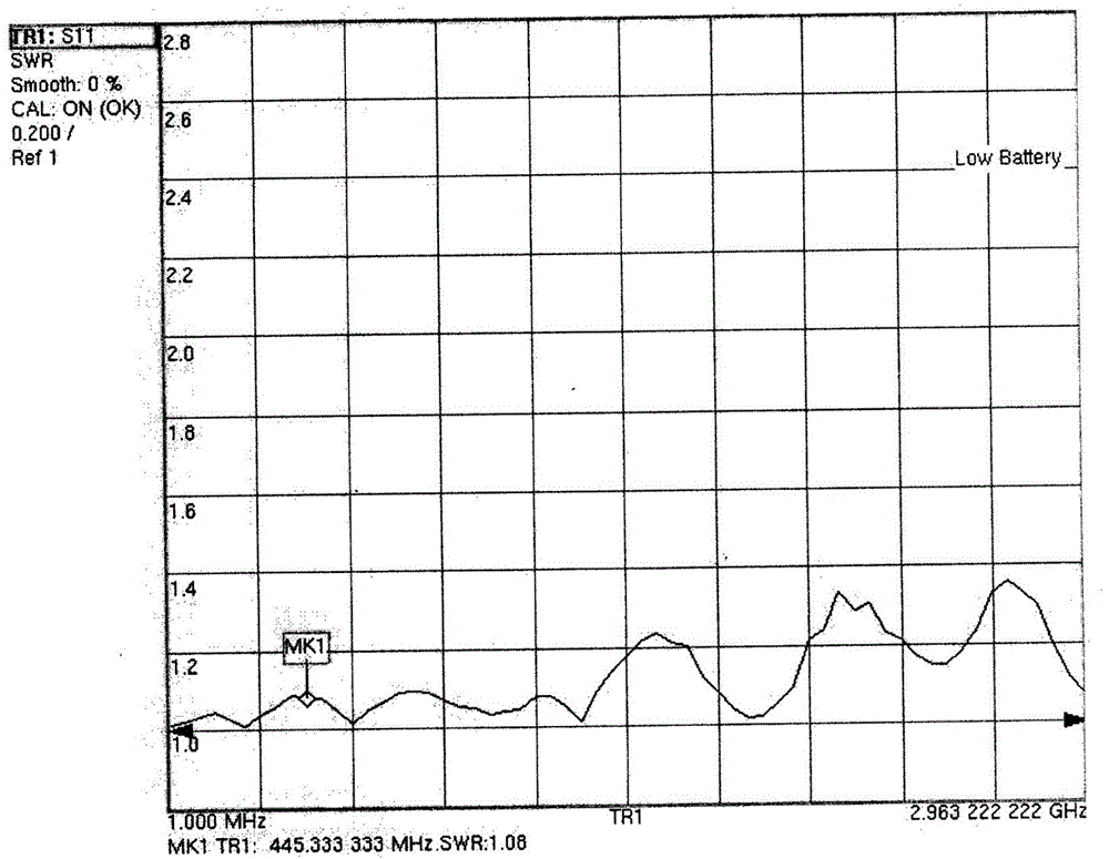
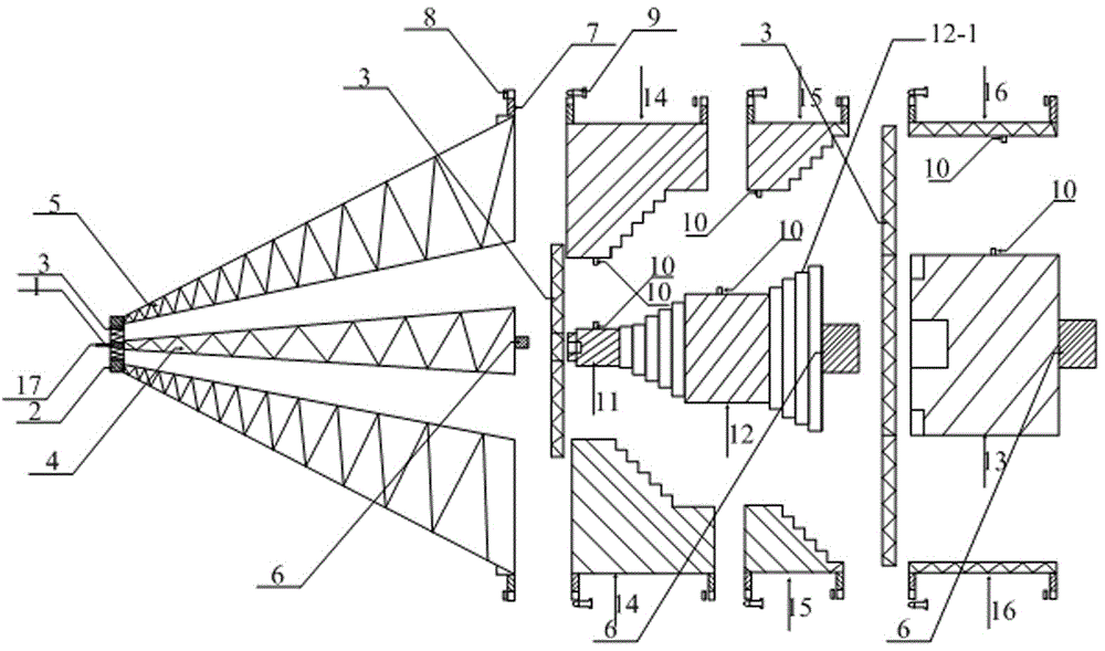

Image

  • Multi-section gradually-changing coaxial type component high-voltage fast pulse response test fixture
  • Multi-section gradually-changing coaxial type component high-voltage fast pulse response test fixture
  • Multi-section gradually-changing coaxial type component high-voltage fast pulse response test fixture

Examples


Embodiment Construction

[0022] Such as figure 1 As shown: it is a closed metal shield as a whole, mainly including a coaxial fixture with a gradient structure of three parts: the left end part, the right end part and the middle part; the left and right ends are tapered cone structures with the same structure, symmetrically arranged On both sides of the middle part; the left and right end parts respectively include the tapered inner conductor 4 and the tapered outer conductor 5, the diameters of the tapered inner conductor 4 and the tapered outer conductor 5 are combined from the end to the middle part The part is a gradually increasing cone structure, and the ends of the tapered inner conductor 4 and the tapered outer conductor 5 are respectively connected with an extended inner conductor 1 and an extended outer conductor 2 with equal diameters.

[0023] The middle part is a cylindrical coaxial structure as a whole, which includes a left coaxial part, a right coaxial part and a middle coaxial part. T...


PUM


Abstract

The invention discloses a multi-section gradually-changing coaxial type component high-voltage fast pulse response test fixture. The multi-section gradually-changing coaxial type high-voltage component fast pulse response test fixture is a closed coaxial metal shielding body on the whole. The closed coaxial metal shielding body mainly comprises a coaxial fixture of which the left end part, the right end part and the middle part are of gradually-changing structures; the left end part and the right end part are of the same gradually-changing cone structure and are symmetrically arranged at two sides of the middle part; the middle part is a cylindrical coaxial fixture on the whole and comprises a left section coaxial part, a right section coaxial part and a middle section coaxial part, wherein the left section coaxial part and the right section coaxial part are of the same structure and are symmetrically arranged at two sides of the middle section coaxial part; the outer surfaces of inner conductors and the inner walls of outer conductors of the middle part of the fixture are oppositely provided with test device welding points; and inner and outer diameter axial displacement compensation is carried out on portions on the middle part of the fixture, wherein the portions are transitional portions from the equal-diameter conductors to the gradually-changing cones, and therefore, the decrease of the transmission performance of high-frequency signals which is caused by sharp change of radius can be reduced. The multi-section gradually-changing coaxial type component high-voltage fast pulse response test fixture of the invention has the advantages of high innovativeness and structural simplicity. The size of each part is relatively fixed, and the parts can be flexibly disassembled, and standardized production and batch processing can be facilitated. The multi-section gradually-changing coaxial type component high-voltage fast pulse response test fixture has a bright popularization and application prospect.

Description

technical field [0001] The invention relates to the technical field of a coaxial test fixture, in particular to a multi-section gradual change coaxial component high voltage fast pulse response test fixture. Background technique [0002] The development of high-power electromagnetic pulse weapons has caused serious threats to the safety of electronic power systems. The characteristics of high-power electromagnetic pulses are high power, fast pulse rise time, and wide frequency band. Compared with lightning electromagnetic pulses, high-power electromagnetic pulses such as nuclear electromagnetic pulses, high-power microwaves, and ultra-broadbands have rich high-frequency components, and their rising edges can reach ns or even sub-ns levels. There are two main attack methods of high-power electromagnetic pulses on electrical and electronic equipment. One is to directly couple into the interior of the equipment through the openings and gaps of the equipment casing to cause dama...

Claims


Application Information

Patent Timeline
IPC IPC(8): G01R1/04
CPCG01R1/0425
Inventor 张耀辉黄刘宏姜彦南李跃波张俊刘锋杨杰王娇
Owner UNIT 61489 OF PLA
Learn More