Inter-pressure counter-rotating impeller mechanism

An impeller, forward rotation technology, applied in the field of inter-pressure and counter-rotating impeller mechanisms, can solve problems such as shock waves and limited application, and achieve the effects of high efficiency, reduction of stages, and simple structure

Inactive Publication Date: 2016-08-24
SHANGLING CO LTD
View PDF7 Cites 1 Cited by
  • Summary
  • Abstract
  • Description
  • Claims
  • Application Information

AI Technical Summary

Problems solved by technology

[0002] Whether it is an impeller compressor or a turbine, it usually requires many stages. If the speed is too high, flow loss will occur. Although there is a counter-rotating structure that can increase the power per unit weight of the impeller mechanism and reduce the cost, but due to direct counter-rotation in many cases The shock wave phenomenon and other reasons will be generated under the environment, and the application has been limited

Method used


Image

  • Inter-pressure counter-rotating impeller mechanism
  • Inter-pressure counter-rotating impeller mechanism
  • Inter-pressure counter-rotating impeller mechanism

Examples


Embodiment 1

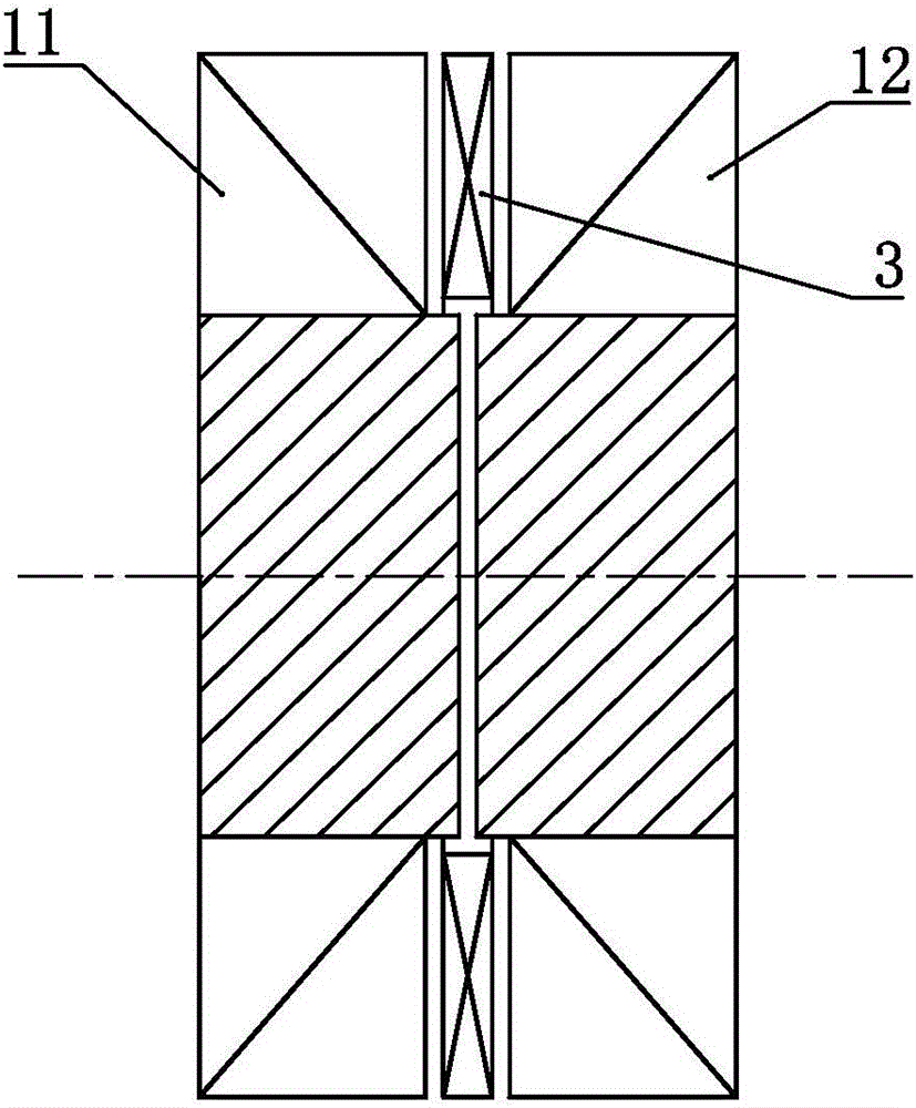
[0031] like figure 1 The shown inter-pressure counter-rotating impeller mechanism includes a forward-rotating impeller 11 and a counter-rotating impeller 12, and the forward-rotating impeller 11 and the counter-rotating impeller 12 are arranged correspondingly. A booster channel 3 is provided between 12.

[0032] In this embodiment, both the forward-rotating impeller 11 and the counter-rotating impeller 12 are of axial flow type.

Embodiment 2

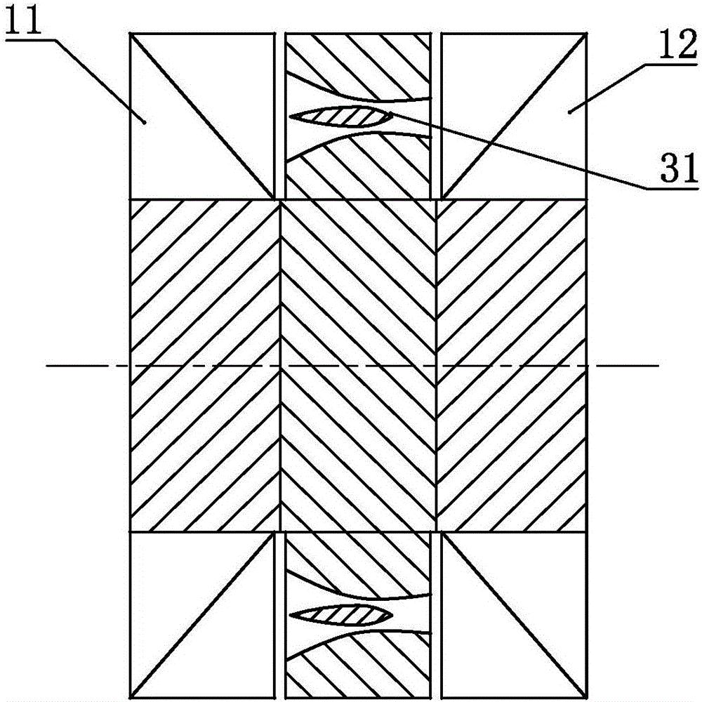
[0034] like figure 2 In the shown inter-pressure counter-rotating impeller mechanism, on the basis of Embodiment 1, the boosting channel 3 is set as a punching channel 31 .

Embodiment 3

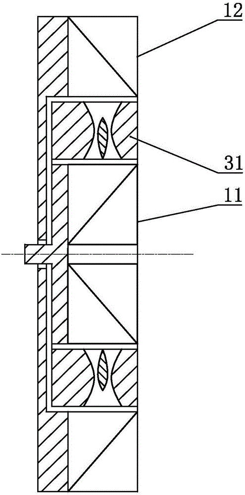
[0036] like image 3 The difference between the shown inter-pressure counter-rotating impeller mechanism and Embodiment 1 is that the forward-rotating impeller 11 and the counter-rotating impeller 12 are set as radial flow, and the boosting channel 3 is set as a stamping Channel 31.


PUM


Abstract

The invention discloses an inter-pressure counter-rotating impeller mechanism. The mechanism comprises forward impellers and reverse impellers. The forward impellers and the reverse impellers are arranged correspondingly. Pressure-raising runners are arranged between the forward impellers and the reverse impellers. According to the inter-pressure counter-rotating impeller mechanism disclosed by the invention, by arranging the pressure-raising runners, the stage number of a conventional impeller mechanism can be reduced, and the mechanism used for a counter-rotating mechanism can weaken shock waves and has the advantages of simple structure and high efficiency.

Description

technical field [0001] The invention relates to the field of thermal energy and power, in particular to an inter-pressure counter-rotating impeller mechanism. Background technique [0002] Whether it is an impeller compressor or a turbine, it usually requires many stages. If the speed is too high, flow loss will occur. Although there is a counter-rotating structure that can increase the power per unit weight of the impeller mechanism and reduce the cost, but due to direct counter-rotation in many cases The application has been limited due to the shock wave phenomenon and other reasons. Therefore need to invent a kind of novel impeller mechanism. Contents of the invention [0003] In order to solve the above problems, the technical scheme proposed by the present invention is as follows: [0004] Scheme 1: An inter-pressure counter-rotating impeller mechanism, including a forward-rotating impeller and a counter-rotating impeller, the forward-rotating impeller and the count...

Claims


Application Information

Patent Timeline
Patent Type & Authority Applications(China)
IPC IPC(8): F01D1/28F01D1/26F04D29/28
CPCF01D1/28F01D1/26F04D29/285F04D29/321
Inventor 靳北彪
Owner SHANGLING CO LTD
Why Eureka
Try Eureka