Drainage device for shallow silt foundation treatment and laying method

A technology of silt foundation and drainage device, which is applied in soil protection, infrastructure engineering, construction, etc., can solve the problems of long detection time, breakage, silting, etc., to improve sensitivity and accuracy, increase strength and stability, Not easy to deform and break

Active Publication Date: 2016-08-24
ZHEJIANG UNIV OF WATER RESOURCES & ELECTRIC POWER
View PDF4 Cites 6 Cited by
  • Summary
  • Abstract
  • Description
  • Claims
  • Application Information

AI Technical Summary

Problems solved by technology

[0003] However, there are obvious defects in this method. Only relying on the drainage board for drainage, the drainage area is small and the efficiency is low. The drainage board has been buried in soft soil for a long time without being fixed, and it is easy to deform with the soil or even break, which greatly affects its performance. Drainage performance
During the drainage process of the shallow silt foundation, after the water with fine soil particles passes through the holes of the drainage plate and is discharged along the drainage pipe, some soil particles are easy to block the drainage holes of the drainage plate, and the other part of the soil particles that pass through the drainage holes Silt and silt enter the drainage pipe along the water flow, and it is easy to deposit in the drainage pipe, causing silting, hindering water penetration, deteriorating drainage effect, and finally leading to poor soil reinforcement effect
Since the drainage pipes are buried in the ground, there are a large number of them. Once the drainage pipes are clogged, it is difficult to find out the specific clogged pipes. It is necessary to check and check one by one. The detection time is long and the efficiency is low.

Method used


Image

  • Drainage device for shallow silt foundation treatment and laying method
  • Drainage device for shallow silt foundation treatment and laying method
  • Drainage device for shallow silt foundation treatment and laying method

Examples


Embodiment Construction

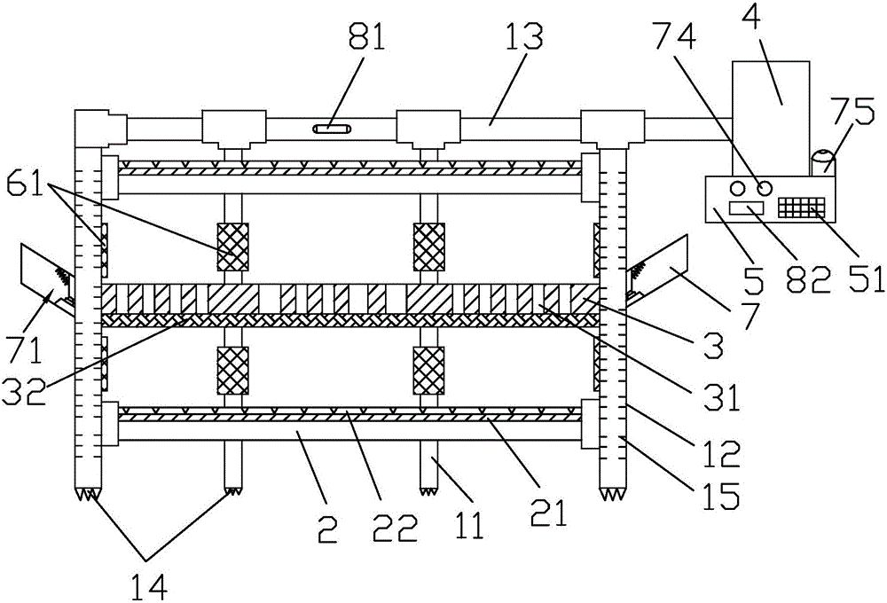
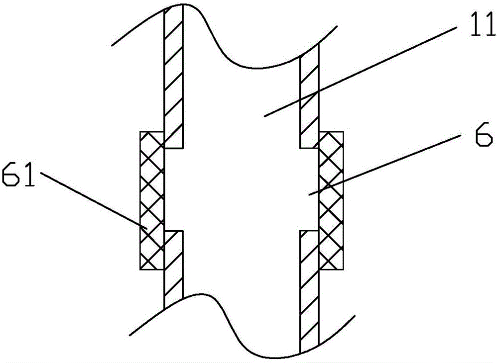
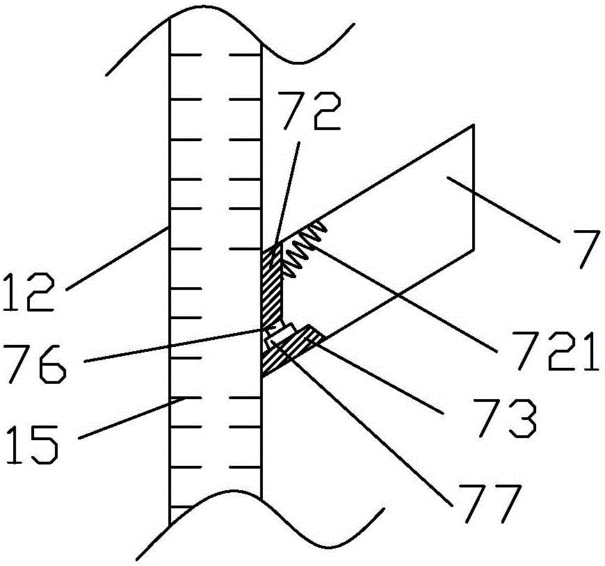
[0049] Such as Figure 1-4 Shown here is a drainage device for shallow silt foundation treatment of the present invention, including drainage pipes, drainage plates 2, mesh screens 3, vacuum equipment 4 and console 5, and the drainage pipes include main drainage pipe 11, auxiliary The drainage pipe 12 and the connecting pipe 13, the drainage plate 2 and the grid screen 3 are spaced from bottom to top, and multiple drainage plates 2 and grid screens 3 are arranged to improve drainage efficiency, increase the strength of the foundation, and reduce the clogging of silt during drainage. . A geotextile 21 and a woven fabric 22 are laid on the top of the drainage plate 2. The geotextile 21 is located on the upper side of the drainage plate 2, and the woven fabric 22 is located on the upper side of the geotextile 21. A layer of filter geotextile 21 is laid on the top surface of the drainage board 2 to prevent the passage of soil particles, so as to prevent the drainage channel from be...


PUM


Abstract

The invention mainly discloses a drainage device for shallow silt foundation treatment. The drainage device has the technical scheme that the drainage device comprises drainage pipelines, vacuum equipment, a drainage board and a gridding screen, wherein the drainage board and the gridding screen are arranged at an interval from bottom to top, the drainage pipelines are respectively connected to the middle and both ends of the drainage board and the gridding screen, water inlet holes with microfiltration membranes are respectively formed in the pipe walls of a main drainage pipe and a secondary drainage pipe, and blockage detection devices are arranged on the side walls of the drainage pipelines. The method comprises the following steps of (1) preparing for construction; (2) partitioning a foundation; (3) laying the drainage board and the gridding screen; (4) laying the drainage pipelines; (5) installing the blockage detection devices; (6) installing a water flow sensor; (7) burying observation equipment; (8) performing vacuum drainage. The drainage device has the effects of high drainage efficiency, difficulty in blocking the drainage pipelines, convenience in checking blocked drainage pipelines, time saving, labor saving, energy conservation, environmental friendliness and cost saving, and the bearing capacity of the foundation is increased.

Description

Technical field [0001] The invention relates to a drainage device and an arrangement method for shallow silt foundation treatment. Background technique [0002] At present, soft clay layers are widely distributed in the southeast coastal areas of my country, with high water content, large void ratio, high compressibility, poor water permeability, low strength, long consolidation time, high sensitivity, large disturbance, and foundation bearing capacity. The stability often fails to meet engineering requirements, or even in a fluid state. Such foundations usually require treatment measures to increase the bearing capacity of the foundation. Drainage consolidation method is currently the main method for soft soil foundation treatment, and vacuum preloading method is the most widely used treatment method. The vacuum preloading method is to lay a sealing film on the surface of the foundation, vacuum through special vacuum equipment, and lay a drainage plate and drainage channel on th...

Claims


Application Information

Patent Timeline
IPC IPC(8): E02D3/10
CPCE02D3/10E02D3/103E02D2600/10
Inventor 徐国梁周旭杰袁明炜
Owner ZHEJIANG UNIV OF WATER RESOURCES & ELECTRIC POWER
Why Eureka
Try Eureka