
A wheel back chamber deburring device

A deburring and back cavity technology, which is applied in the direction of grinding drives, grinding machines, grinding machine parts, etc., can solve the problems that the wheels cannot meet the removal requirements, there is no ideal removal method, and the burr brushing method is single. The effect of high degree of automation, safe performance and strong versatility

Active Publication Date: 2018-03-20
CITIC DICASTAL
View PDF5 Cites 0 Cited by
  • Summary
  • Abstract
  • Description
  • Claims
  • Application Information

AI Technical Summary

Problems solved by technology

[0002] For manufacturers of aluminum alloy wheels, there is still no ideal way to remove the burrs formed after machining. The traditional burr brushing equipment has a single method of brushing burrs, which cannot meet the removal requirements for wheels with complex shapes; and , for the vast majority of production enterprises now carry out mixed-line production, that is, there are wheels of different sizes circulating in each process on the production line at the same time, which is a very big limitation for the brushing equipment room
When switching wheels of different sizes, the corresponding brush system must be replaced, which seriously affects the production efficiency

Method used


Image

  • A wheel back chamber deburring device
  • A wheel back chamber deburring device
  • A wheel back chamber deburring device

Examples


Embodiment Construction

[0017] The details and working conditions of the specific device proposed according to the present invention will be described below in conjunction with the accompanying drawings.

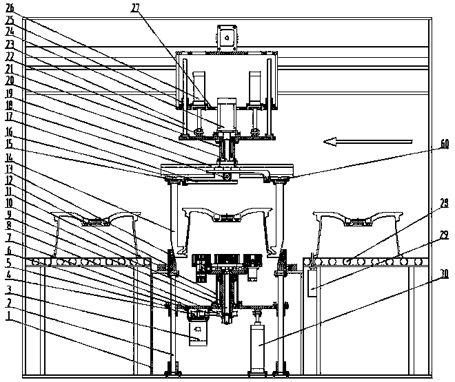
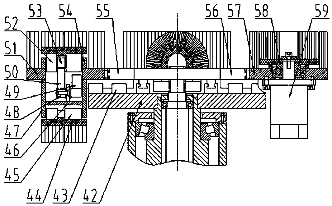
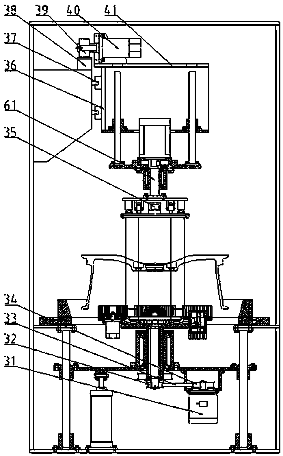
[0018] The device consists of a frame 1, a lower guide column 2, a motor I3, a pulley I4, a lower guide sleeve 5, a lower lifting plate 6, a synchronous belt I7, a pulley II8, a central shaft 9, a lower rotating shaft 10, a lower bearing seat 11, Turntable 12, tapered sleeve 13, claw 14, left slide plate 15, guide rail Ⅰ16, rack Ⅰ17, gear Ⅰ18, rotating plate 19, upper shaft 20, upper bearing seat 21, upper lifting plate 22, upper guide column 23, motor Ⅱ24 , Upper guide sleeve 25, Upper cylinder 26, Lower plate 27, Roller table 28, Stopper 29, Lower cylinder 30, Motor III 31, Pulley III 32, Timing belt II 33, Pulley IV 34, Clamping cylinder 35, Vertical plate 36, Horizontal guide rail 37, rack II 38, gear II 39, servo motor I 40, top plate 41, bottom plate 42, guide rail II 43, brush I 44, lower br...


PUM


Abstract

The invention relates to a wheel back chamber deburring device, which is composed of a frame, a clamping and rotating system, a lifting and translation system and a brush unit. The jaws clamp the wheel on the roller table, the upper cylinder lifts the wheel through the four upper guide columns, the servo motor I moves the wheel to the top of the tapered sleeve through the rack II and the gear II; the upper cylinder lowers the wheel, and the four jaws The outer side of the motor is matched with the tapered sleeve; the motor Ⅱ makes the wheel rotate in the clamped state; the motor Ⅰ drives the base plate and the brush system to rotate in the circumferential direction through the synchronous belt Ⅰ; the servo motor Ⅱ drives the brush Ⅰ to rotate, and the servo motor Ⅲ drives When the brush II rotates, the bristles of the two brushes form brushing forces in different directions on the back cavity of the wheel; the rotation direction of the wheel is opposite to that of the brush system; the lower cylinder raises the brush system through the lower guide column and touches the wheel Deburring can be carried out when the cavity is back.

Description

technical field [0001] The invention relates to a deburring device, in particular to a wheel back chamber deburring device capable of automatically adjusting the size of a brush system. Background technique [0002] For manufacturers of aluminum alloy wheels, there is still no ideal way to remove the burrs formed after machining. The traditional burr brushing equipment has a single method of brushing burrs, which cannot meet the removal requirements for wheels with complex shapes; and , For most of the current production enterprises, they carry out mixed-line production, that is, there are wheels of different sizes circulating in various processes on the production line at the same time, which is a very big limitation for the deburring equipment room. When switching wheels of different sizes, the corresponding brush system must be replaced, which seriously affects the production efficiency. Contents of the invention [0003] The purpose of the present invention is to prov...

Claims


Application Information

Patent Timeline
Patent Type & Authority Patents(China)
IPC IPC(8): B24B9/04B24B41/06B24B47/12B24B41/00
CPCB24B5/44B24B9/04B24B29/005B24B41/00B24B41/06B24B47/10
Inventor 薛博文郭建东
Owner CITIC DICASTAL
Learn More