
Optical module

A technology of optical modules and laser receivers, applied in the field of optical communications, to achieve the effects of solving large interference, improving sensitivity and reducing costs

Inactive Publication Date: 2016-08-17
HISENSE BROADBAND MULTIMEDIA TECH
View PDF6 Cites 6 Cited by
  • Summary
  • Abstract
  • Description
  • Claims
  • Application Information

AI Technical Summary

Problems solved by technology

At present, this kind of scheme is becoming more and more mature. The performance and quality of the products of various module manufacturers are very close, and the price war is intensifying. This kind of design scheme has no room for price reduction except for the price reduction of chips and BOSA resources.

Method used


Image

  • Optical module
  • Optical module
  • Optical module

Examples


Embodiment Construction

[0030] In order to make the purpose, technical solutions and advantages of the embodiments of the present invention clearer, the technical solutions in the embodiments of the present invention will be clearly and completely described below in conjunction with the drawings in the embodiments of the present invention. Obviously, the described embodiments It is a part of embodiments of the present invention, but not all embodiments. Based on the embodiments of the present invention, all other embodiments obtained by persons of ordinary skill in the art without creative efforts fall within the protection scope of the present invention.

[0031] The optical module provided by the embodiment of the present invention can be applied to the ONU in the GPON network to achieve high-speed, long-distance transmission; of course, it can also be applied to other passive optical networks (Passive Optical Network, referred to as PON), such as: Ethernet In the ONU in the passive optical network...


PUM


Abstract

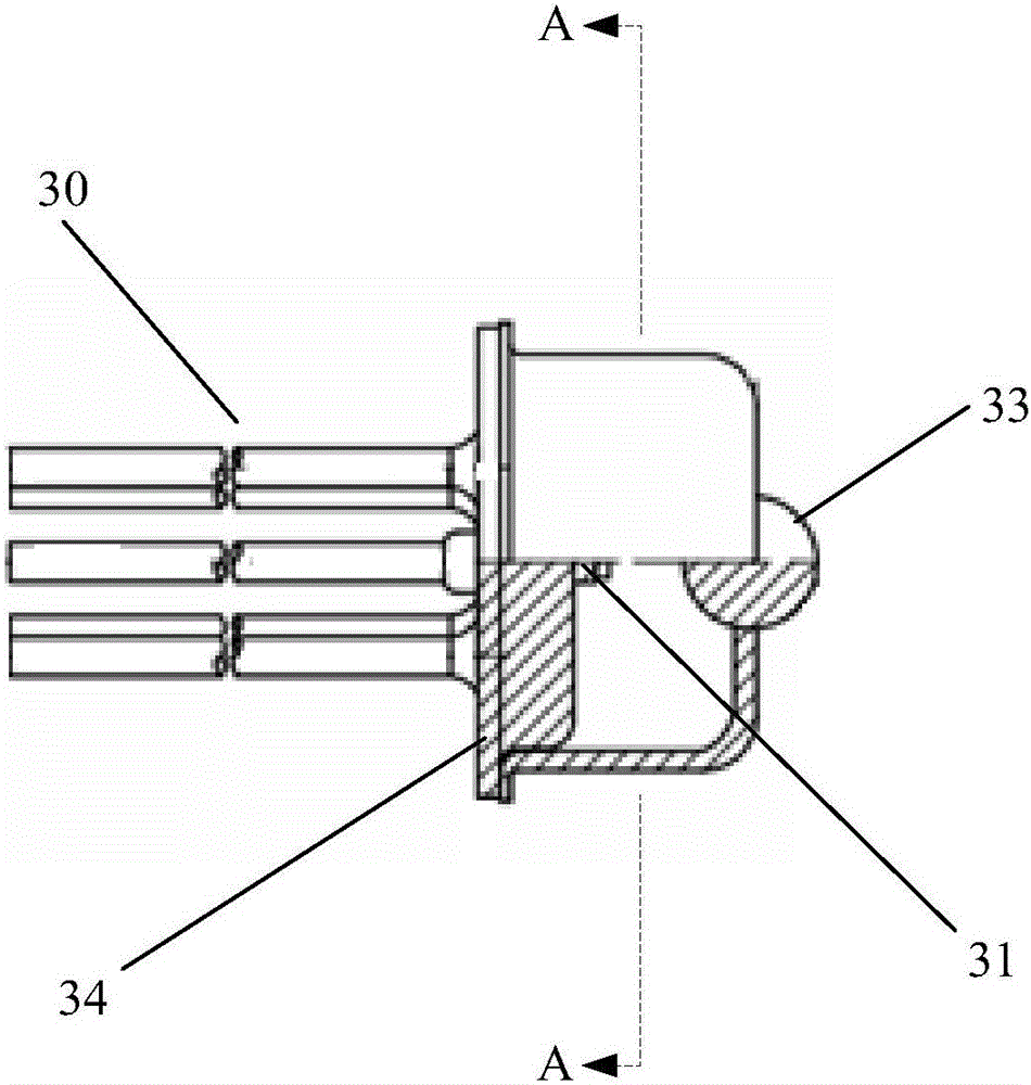
The invention provides an optical module. The optical module comprises a main control chip, and a laser transmitter and a laser receiver connected with the main control chip. The laser receiver comprises a PIN photoelectric diode, a trans-impedance amplifier of which trans-impedance is not less than 43Kohms, a lens and a shell. The PIN photoelectric diode is electrically connected with the trans-impedance amplifier. The PIN photoelectric diode, the trans-impedance amplifier and the lens are packaged in the shell through adoption of a transistor out-line mode. Antireflection film is pated on the lens. According to the optical module, high sensitivity remote transmission of a GPON (Gigabit-Capable Passive Optical Network) network is realized through combination of the PIN photoelectric diode and the high gain trans-impedance amplifier instead of an APD (Avalanche Photo Diode), therefore the cost is effectively reduced; various disadvantages such as high interference and low stability resulting from realizing the high sensitivity remote transmission by using the APD at present are solved; moreover, the antireflection film is pated on the lens of the laser receiver, therefore the reflection of the receiving light is reduced, the transmission light is increased, and the sensitivity is improved.

Description

technical field [0001] The invention relates to optical communication technology, in particular to an optical module. Background technique [0002] With the rapid development of the Internet, people's demand for network resources is increasing rapidly, and the deployment scale of Fiber To The Home (FTTH for short) is also increasing. As the core component of the optical fiber communication system—the optical module, due to the massive demand for it in the world, the cost control of the optical module is particularly important in the entire process of R&D and production of the optical module. [0003] The passive optical access system (Gigabit-Capable PON, GPON for short) optical network unit (Optical Network Unit, ONU for short) optical module with digital diagnostic function is the mainstream product in the market in recent years, and its internal hardware design mostly adopts integrated launch , receiving, and control integrated chip with distributed feedback laser (Distr...

Claims


Application Information

Patent Timeline
Patent Type & Authority Applications(China)
IPC IPC(8): H04B10/50H04B10/67H04B10/69G02B6/42
CPCG02B6/428G02B6/4296H04B10/503H04B10/67H04B10/69G02B6/4274H04B10/40G02B6/00H04B10/60
Inventor 董雅倩郑龙张华
Owner HISENSE BROADBAND MULTIMEDIA TECH
Learn More