
Gate drive circuit

A gate drive circuit and drive signal technology, applied in static indicators, instruments, etc., can solve the problems of gate drive circuit re-operating normally, components are prone to aging, etc., and achieve the effect of avoiding rapid aging

Inactive Publication Date: 2019-01-04
AU OPTRONICS CORP
View PDF6 Cites 0 Cited by
  • Summary
  • Abstract
  • Description
  • Claims
  • Application Information

AI Technical Summary

Problems solved by technology

But at the same time, how to enable the gate drive circuit to resume normal operation after the touch sensing period has become a problem that must be considered when designing the gate drive circuit
On the other hand, since the components of the gate drive circuit are susceptible to long-term bias stress (voltage stress) under such a structure, the components in the gate drive circuit are also prone to aging problems.

Method used


Image

  • Gate drive circuit
  • Gate drive circuit
  • Gate drive circuit

Examples


Embodiment Construction

[0055] The detailed features and advantages of the present invention are described in detail below in the embodiments, which are sufficient for any person familiar with the relevant art to understand the technical content of the present invention and implement it accordingly, and according to the contents disclosed in this specification, claims and accompanying drawings, The related objects and advantages of the present invention can be easily understood by anyone skilled in the relevant art. The following examples further illustrate the concept of the present invention in detail, but do not limit the scope of the present invention in any way.

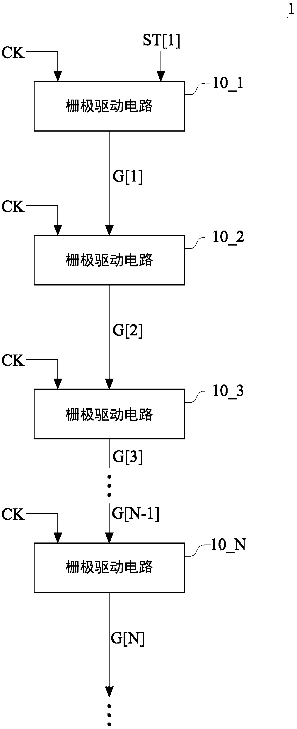
[0056] Please refer to figure 1 , figure 1 It is a schematic functional block diagram of a gate driver according to an embodiment of the present invention. Such as figure 1 As shown, the gate driver 1 includes gate drive circuits 10_1 - 10_N . . . Wherein, N is a positive integer greater than 3. In this embodiment, the gate drivin...


PUM


Abstract

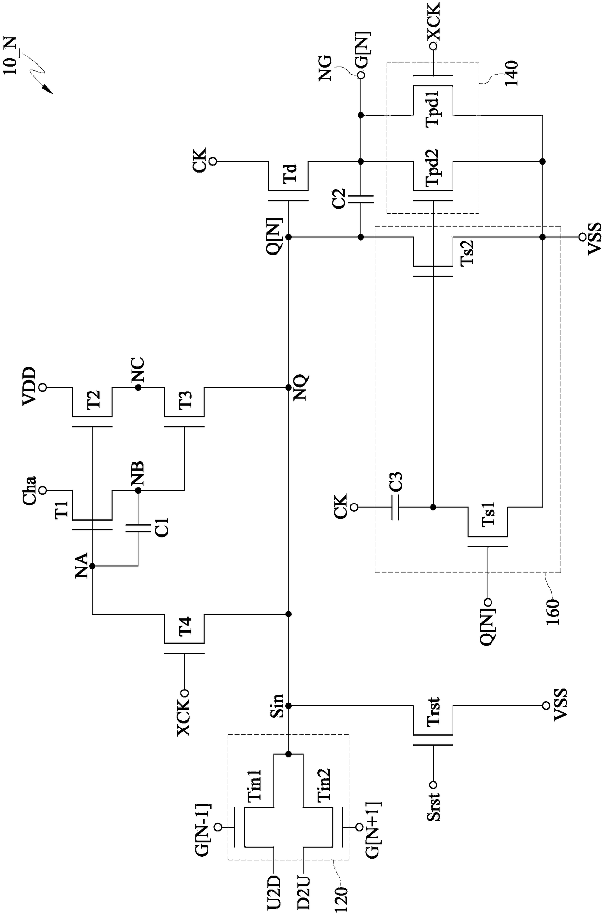
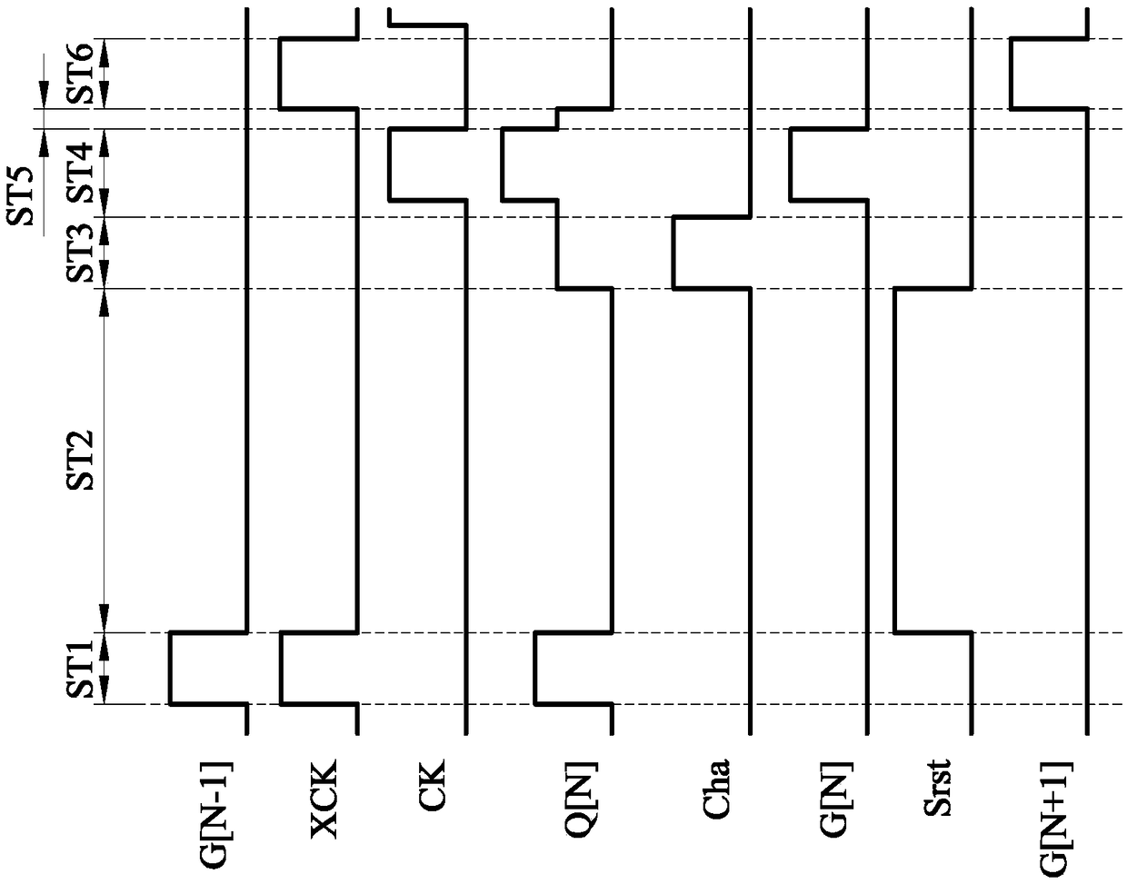
The invention provides a grid electrode drive circuit comprising a drive switch, an input module, a pull down module, a first switch, a second switch, a third switch, a capacitor and a reset switch; the drive switch is controlled by a first node voltage level; the input module is coupled to the first node; the pull down module is coupled to one end of the drive switch; two ends of the first node are respectively coupled to a charging signal end and a second node, and a control end is coupled to a storage node; two ends of the second switch are respectively coupled to a second reference voltage end and a third node, and a control end is coupled to the storage node; two ends of the third switch are respectively coupled to a third node and the first node, and a control end is coupled to the second node; two ends of the capacitor are respectively coupled to the storage node and the second node; two ends of the reset switch are respectively coupled to the first node and the first reference voltage end, and a control end is coupled to the reset signal end; a desired grid electrode drive signal is re-generated after a touch control sensing period, thus preventing elements in the grid electrode drive circuit from fast aging by the long time biased stress influence.

Description

technical field [0001] The present invention relates to a gate drive circuit, in particular to a gate drive circuit for recharging a node to output a gate drive signal after a touch detection stage. Background technique [0002] With the evolution of technology, today's panels often integrate display and touch functions to provide users with a convenient operation interface. In an in-cell touch panel, the in-cell touch panel is provided with a gate drive circuit and a touch control circuit on the same substrate, and the gate drive signal line and the touch signal line may be in contact with each other. Very close, so the gate drive signal and the touch signal will interfere with each other. Due to the strong strength of the gate driving signal, through the capacitive coupling effect, the gate driving signal often causes noise and interferes with the touch signal, thereby reducing the signal to noise ratio (SNR) of the touch operation. [0003] In the traditional practice, ...

Claims


Application Information

Patent Timeline
Patent Type & Authority Patents(China)
IPC IPC(8): G09G3/20
CPCG09G3/20
Inventor 林志隆赖柏成赖柏君柯健专蔡孟杰陈勇志
Owner AU OPTRONICS CORP
Learn More