
Solar cell array maximum power tracking hardware circuit

A technology of maximum power tracking and solar cell array, applied in photovoltaic power generation, adjusting electric variables, instruments, etc., can solve the problem of poor radiation resistance and reliability of MPPT algorithm, and cannot adapt to the needs of space high reliability applications, and cannot adapt to space applications Requirements and other issues, to achieve the effect of improving radiation resistance, good reliability, and easy realization

Inactive Publication Date: 2016-08-17
SHANGHAI INST OF SPACE POWER SOURCES
View PDF7 Cites 6 Cited by
  • Summary
  • Abstract
  • Description
  • Claims
  • Application Information

AI Technical Summary

Problems solved by technology

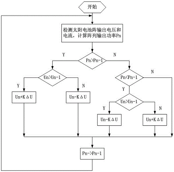
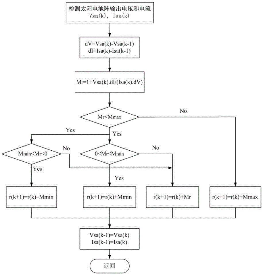
[0003] The traditional MPPT algorithm generally adopts such as figure 1 perturbation method as shown, or using a method such as figure 2 Incremental conductance method shown by figure 1 and figure 2 It can be seen that the traditional MPPT algorithm needs to collect the output voltage and current of the solar array, and after calculating the output power, perform a series of logical judgments to generate the MPPT control signal. The traditional MPPT algorithm needs a multiplier and divider, which is suitable for software implementation and cannot adapt to space radiation. The application requirements in the environment, and the traditional MPPT algorithm has a △V step disturbance, which cannot meet the application requirements of high reliability in space
[0004] Due to its poor radiation resistance and reliability, the traditional MPPT algorithm cannot meet the needs of space applications

Method used


Image

  • Solar cell array maximum power tracking hardware circuit
  • Solar cell array maximum power tracking hardware circuit
  • Solar cell array maximum power tracking hardware circuit

Examples


Embodiment Construction

[0035]based on the following image 3 and Figure 4 , specifically describe the preferred embodiment of the present invention.

[0036] Such as image 3 As shown, the present invention provides a solar cell array maximum power tracking hardware circuit, comprising: a signal source 1, a differential module 2 electrically connected to the signal source 1, a voltage divider module 3 electrically connected to the differential module 2, The switch energy storage module 4 of the pressure module 3 is electrically connected to the voltage comparison module 5 of the switch energy storage module 4, and the reset module 6 is electrically connected to the switch energy storage module 4, the voltage comparison module 5 and the reset module 6. A logic selection module 7, and a filter module 8 electrically connected to the set reset module 6 and the logic selection module 7.

[0037] Such as Figure 4 As shown, in one embodiment of the present invention, the input end of the solar cell a...


PUM


Abstract

A solar cell array maximum power tracking hardware circuit comprises a differential module, a voltage division module, a switch energy storage module, a voltage comparison module, a setting and resetting module, a logic selection module and a filter module. The differential module is electrically connected with solar array output voltage VSA and solar array output current ISA, the voltage division module is electrically connected with the differential module, the switch energy storage module is electrically connected with the voltage division module, the voltage comparison module is electrically connected with the switch energy storage module, and the filter module is electrically connected with the setting and resetting module and the logic selection module. On the basis of inherent characteristics of a solar array output characteristic curve, voltage and current are disturbed alternately, maximum power tracking can be realized simply, quickly and efficiently; an algorithm has no direct relation with power, multiply-divide operation is not needed, and the hardware circuit is easy to realized; disturbance is continuous, and the hardware circuit has better reliability, so that anti-radiation characteristics of MPPT algorithm control signals are improved; the hardware circuit has autonomy and high accuracy, can quickly and accurately track maximum power point and adapts to space application needs.

Description

technical field [0001] The invention relates to the technical field of aerospace power supply control, in particular to a solar cell array maximum power tracking hardware circuit. Background technique [0002] Power transmission technology is an important part of space power system technology. Power transmission methods include direct energy (DET) transmission and maximum power tracking (MPPT) transmission. The MPPT method can maximize the use of the output power of the solar array. The MPPT algorithm is an important part of the MPPT method. [0003] The traditional MPPT algorithm generally adopts such as figure 1 perturbation method as shown, or using a method such as figure 2 Incremental conductance method shown by figure 1 and figure 2 It can be seen that the traditional MPPT algorithm needs to collect the output voltage and current of the solar array, and after calculating the output power, perform a series of logical judgments to generate the MPPT control signal...

Claims


Application Information

Patent Timeline
IPC IPC(8): G05F1/67
CPCG05F1/67Y02E10/56
Inventor 刘绘莹何小斌蓝建宇董宇陈杰刘勇
Owner SHANGHAI INST OF SPACE POWER SOURCES
Learn More