Setting-out device for ceiling roof

A pay-off device and coil technology, which is applied in the field of measurement, can solve the problems of affecting the construction period, inconvenient use, and delays in work by operators, so as to achieve the effects of saving equipment investment, reducing costs, and avoiding delays in work

Active Publication Date: 2016-08-17
CHINA MCC17 GRP
View PDF6 Cites 1 Cited by
  • Summary
  • Abstract
  • Description
  • Claims
  • Application Information

AI Technical Summary

Problems solved by technology

[0002] At present, in the construction process of construction projects, in order to make reasonable use of space, there are a lot of equipment and pipelines arranged on the ceiling. Personnel working on the side construction or setting up the operation platform use the ink fountain to set out the line, and even use the feeling to locate, but there are the following problems: 1. The environment for using the laser vertical instrument must be in a certain degree of darkness, otherwise it cannot be seen or seen clearly, so it is used during the day extremely inconvenient
2. Since the construction of the ceiling requires a lot of time, and there are many operating points and a wide area, it is necessary to increase the number of operating instrument personnel to follow up the measurement, resulting in sufficient equipment and equipment, and at the same time increasing the workload of the surveyors
3. Once the number of surveyors cannot meet the requirements of construction work points, it will cause workers to miss work and affect the construction period
4. Using the ink fountain to set off the wire requires an operation platform, which requires a large workload and is inconvenient for the operator
5. Relying on the feeling of construction, the construction pipeline of the ceiling is chaotic, unsightly, and even affects the construction quality

Method used


Image

  • Setting-out device for ceiling roof

Examples


Embodiment

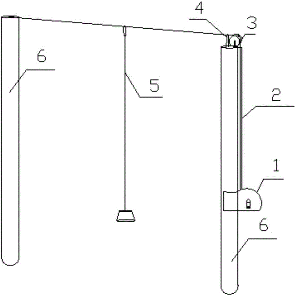
[0014] Example: such as figure 1 As shown, the present invention provides a ceiling wire pay-off device, which includes an ink fountain 1, the ink fountain 1 has a built-in coil, and a transfer shaft is arranged in the middle of the coil. Pipe 2, pulley 3, crimping ring 4, spring rope 5, rod top groove and fixed in the center of the rod, the flexible wire pipe 2 is a transparent plastic pipe, the pulley 3 is hardwood, the The crimping ring 4 is a galvanized round steel, the main line of the elastic cord 5 is an elastic rubber material, and the operating rod 6 peripheral hard logs.

[0015] The ink fountain 1 adopts a plastic shell with a thickness of 1 mm. The overall shape is round cake shape. Tight, the ink fountain 1 has a built-in coil, the diameter of the coil is 100mm, one end of the intermediate shaft is extended, and the external rotating handle is installed. The ink fountain 1 is closed, and a small hole with a diameter of 2mm is opened on the upper surface of the ro...


PUM


Abstract

The invention provides a setting-out device for a ceiling roof. The setting-out device comprises an ink fountain. A coil is arranged in the ink fountain. A central rotary shaft is arranged in the center of the coil. A rotary handle is externally arranged at one end of the central rotary shaft. One end of the coil is fixed to the center of a rod through a flexible wire pipe, a pulley, a wire pressing ring, a line snapping rope and a groove in the top end of the rod. The flexible wire pipe is a transparent plastic pipe. The pulley is made of hard wood. The wire pressing ring is made of galvanized round steel. A main rope of the line snapping rope is made of elastic rubber materials. The periphery of an operating rod is made of hard round wood. Compared with a former construction method, the setting-out device is simple and convenient to use, practical and reasonable in structure, the defects of conventional operation are overcome, the construction period is shortened, equipment investment is reduced, the cost is reduced, construction is arranged reasonably through the change of the objective environment, measuring and setting-out as well as installation operation can be implemented independently, and thus construction delay is avoided.

Description

technical field [0001] The invention belongs to the technical field of measurement, and relates to a ceiling wire pay-off device. Background technique [0002] At present, in the construction process of construction projects, in order to make reasonable use of space, there are a lot of equipment and pipelines arranged on the ceiling. Personnel working on the side construction or setting up the operation platform use the ink fountain to set out the line, and even use the feeling to locate, but there are the following problems: 1. The environment for using the laser vertical instrument must be in a certain degree of darkness, otherwise it cannot be seen or seen clearly, so it is used during the day Extremely inconvenient. 2. Since the construction of the ceiling requires a lot of time, and there are many operating points and a wide area, it is necessary to increase the number of operating instrument personnel to follow up the measurement, resulting in sufficient equipment and...

Claims


Application Information

Patent Timeline
Patent Type & Authority Applications(China)
IPC IPC(8): E04G21/18
CPCE04G21/1808
Inventor 郝湖结杨有谊
Owner CHINA MCC17 GRP
Why Eureka
Try Eureka