
Lead core tenon limiting damper system

A damper and lead card technology, applied in construction, bridge construction, bridges, etc., can solve the problems of easy oil leakage, failure to popularize and apply, and no damping effect, etc., and achieve a good limit effect

Inactive Publication Date: 2016-08-17
CHINA RAILWAY ERYUAN ENG GRP CO LTD
View PDF11 Cites 2 Cited by
  • Summary
  • Abstract
  • Description
  • Claims
  • Application Information

AI Technical Summary

Problems solved by technology

However, these current anti-drop beam devices have certain limitations, such as: it is difficult to realize vertical, horizontal, and vertical three-way limit; energy consumption and limit function are separated; energy dissipation capacity is limited; conventional friction pendulum bearings, The shock-absorbing and isolating measures such as hyperboloid spherical shock-absorbing and isolating bearings will fail when the vertical earthquake is strong; the cost is relatively high
In recent years, some scholars have also studied the shock-absorbing tenon, but it has no damping effect.
In addition, some new anti-fall beam devices use some complex structures or new materials, resulting in high costs and cannot be popularized and applied; the process is complicated, the repair after the earthquake is difficult, and the replaceability is poor.
[0003] In addition, locking devices are commonly used in the longitudinal vibration control of beams introduced under impacts such as train braking and traction, but the locking devices have limitations such as high cost, oil leakage, and relatively small damping ratio.

Method used


Image

  • Lead core tenon limiting damper system
  • Lead core tenon limiting damper system
  • Lead core tenon limiting damper system

Examples


Embodiment Construction

[0015] The present invention will be further described below in conjunction with the accompanying drawings and embodiments.

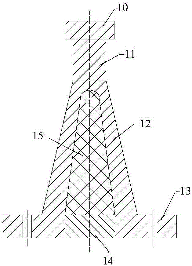
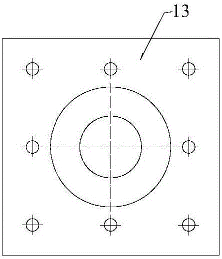
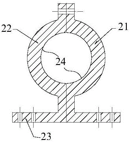
[0016] refer to figure 1 , figure 2 and image 3 , The lead core tenon limit damper system of the present invention includes a steel tenon and a steel buckle. The steel tenon includes a head 10, a buckle fixing section 11, a conical section 12 and an anchor plate 13 from top to bottom, wherein the conical section 12 has a conical cavity, and the conical cavity is filled with With lead core 15. The outer end of the steel tenon is engaged with the buckle fixing section 11 , and the inner end thereof is the bottom plate 23 . refer to Figure 4 and Figure 5 , the steel tenon and the steel buckle are arranged on the outside of the pad stone 32 in the direction of the bridge, and the steel tenon is fixed on the top of the pier body 31 through the high-strength bolt assembly passing through the mounting hole on the anchor plate 13 , the steel buckle i...


PUM


Abstract

A lead core tenon limiting damper system can not only prevent beam bodies from falling off longitudinally and transversely but also achieve vertical limiting of the beam bodies in an earthquake and meanwhile can achieve the effects of seismic reduction and energy dissipation. All assemblies are replaceable modular products so that the assemblies can be conveniently repaired and easily replaced after the earthquake. The lead core tenon limiting damper system comprises a steel tenon and a steel buckle. The steel tenon comprises a head, a buckle fixing section, a tapered section and an anchor plate from top to bottom, wherein a tapered cavity is formed in the tapered section, and a lead core is poured in the tapered cavity. The outer end of the steel buckle embraces the steel buckle fixing section, and a bottom plate is located at the inner end of the steel buckle. The steel tenon and the steel buckle are arranged on the outer side of padstone in the transverse direction of a bridge. The steel tenon is fixedly mounted on the top of a pier body through high-strength bolt assemblies penetrating through mounting holes in the anchor plate of the steel tenon, and the steel buckle is fixedly installed on the side wall of a beam body through high-strength bolt assemblies penetrating through mounting holes in the bottom plate of the steel buckle.

Description

technical field [0001] The present invention relates to bridges, in particular to a lead core tenon limit damper system, which is mainly used in bridges with relative displacement between piers and girders such as simply supported beams, continuous beams (rigid structures), cable-stayed bridges, etc., during earthquakes, Under impact loads such as vehicles (trains), it plays the role of vertical, horizontal, and vertical three-way limit and shock absorption (vibration) energy dissipation, so as to restrain the vibration of the beam body and reduce the distance between the beam body and the beam body, and the beam body and the pier. collision between. Background technique [0002] Simply supported girder bridges, continuous girder (rigid frame) and other girder bridges are the most commonly used bridge types in traffic engineering. The girder drop caused by excessive relative displacement between the girder part and the abutment is the primary cause of bridge collapse in eart...

Claims


Application Information

Patent Timeline
Patent Type & Authority Applications(China)
IPC IPC(8): E01D19/00E01D19/04E01D22/00
CPCE01D19/00E01D19/04E01D22/00
Inventor 曾永平刘鹏樊启武杨国静郑晓龙周帅王典斌陶奇
Owner CHINA RAILWAY ERYUAN ENG GRP CO LTD
Learn More