
A horizontal pressing equipment for rapid prototyping of wind power tower door frame

A technology for wind power towers and door frames, applied to metal processing equipment, etc., to achieve the effects of improving processing progress and work efficiency, convenient operation, and stable performance

Active Publication Date: 2018-04-03
SINOHYDRO BUREAU 14 CO LTD
View PDF6 Cites 0 Cited by
  • Summary
  • Abstract
  • Description
  • Claims
  • Application Information

AI Technical Summary

Problems solved by technology

[0003] The purpose of the present invention is to solve the problems of the press used for door frame forming, the door frame forming mold and the rebound after pressing of the door frame, hoisting, operation and operation safety in the process of pressing the door frame, and provide a horizontal pressing equipment for the rapid prototyping of the wind power tower door frame

Method used


Image

  • A horizontal pressing equipment for rapid prototyping of wind power tower door frame
  • A horizontal pressing equipment for rapid prototyping of wind power tower door frame
  • A horizontal pressing equipment for rapid prototyping of wind power tower door frame

Examples


Embodiment Construction

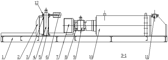
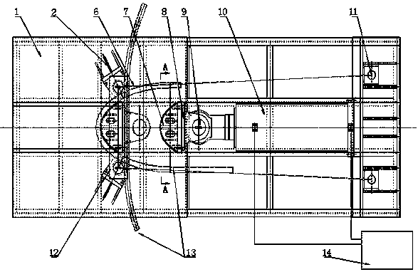
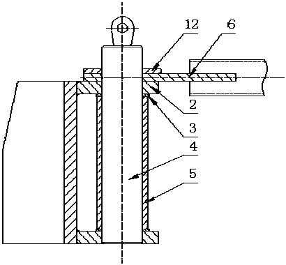
[0025] like figure 1 , 2 As shown, the horizontal pressing equipment of the wind tower door frame press molding of the present invention comprises mold base 1, die base 2, die shaft 4 and die shaft sleeve 5, punch 7, punch hinge seat 8, hinge shaft 9 , transverse pull rod 12, longitudinal pull rod 6, pull rod shaft 11; the die base 2 is welded on the die base 1, and the retaining ring 3 is assembled on the die base 2, and the die shaft 4 is assembled on the die base 2 , the die shaft sleeve 5 is set on the die shaft 4, the punch 7 and the punch hinge seat 8 are connected as a whole by bolts, the punch hinge seat 8 and the hydraulic cylinder 10 are connected by the hinge shaft 9, and one end of the longitudinal tie rod 6 passes through The tie rod shaft 11 is connected to the mold base 1, the other end is connected to the die shaft 4, the transverse tie rod 12 is connected to the upper part of the two die shafts 4, the hydraulic cylinder 10 is connected to the mold base 1, and...


PUM


Abstract

The invention discloses horizontal type compression equipment for rapidly moulding wind tower barrel frames. The horizontal type compression equipment comprises a die holder, a concave die holder, a concave die shaft, a concave die shaft sleeve, a convex die, a convex die hinged support, a hinged shaft, a transverse pull rod, a longitudinal pull rod and a pull rod shaft, wherein the concave die holder is welded on the die holder and connected with the concave die shaft; the concave die shaft sleeve sleeves on the concave die shaft; the convex die and the convex die hinged support are integrally connected through a bolt; the convex die hinged support is connected with a hydraulic oil cylinder through the hinged shaft; one end of the longitudinal pull rod is connected with the die holder through a pull rod shaft and the other end of the longitudinal pull rod is connected with the concave die shaft; the transverse pull rod is connected with upper parts of two concave die shafts; the hydraulic oil cylinder is connected with the die holder and connected with a hydraulic power pack; through the power of the hydraulic oil cylinder, the convex die is pushed to carry out top pressing so as to mould workpieces. The horizontal type compression equipment is convenient to operate, stable in performance, low in noise, safe and reliable in running and long in service life.

Description

technical field [0001] The invention belongs to the technical field of steel structure manufacturing engineering, and in particular relates to a horizontal pressing device for rapid prototyping of a wind power tower door frame. Background technique [0002] At present, the door frame of the wind tower is manufactured according to half-width forming and then welded and assembled. After the door frame is cut according to 1 / 2 of the unfolded length, it is heated by steel plates, hoisted into the mold and pressed into shape by a large-tonnage vertical press. Large-tonnage vertical presses and heating equipment are expensive and low in efficiency. Each door frame must be matched with a corresponding mold. The mold manufacturing cost is high, and it is inconvenient to hoist the workpiece in a hot state. In addition, there is also a plate rolling machine that is gradually rolled and formed. The dimensions of each workpiece after forming are different due to human factors, and the b...

Claims


Application Information

Patent Timeline
Patent Type & Authority Patents(China)
IPC IPC(8): B21D5/06B21D53/74
CPCB21D5/06B21D53/74
Inventor 王德强李有福高兴月童平梁飞马夫斌邓林张玉彬普宝章原河全王文超钟鑫刘凤维陈志高宋敏常鑫王庆来赵建军
Owner SINOHYDRO BUREAU 14 CO LTD
Learn More