An isothermal reactor

A technology of isothermal reactors and heat exchange tubes, applied in chemical instruments and methods, inorganic chemistry, non-metallic elements, etc., can solve the problems of increased equipment costs, untimely heat transfer, waste of materials, etc., to improve catalytic reaction efficiency, Effect of equipment cost reduction

Inactive Publication Date: 2016-08-17
HUNAN ANCHUN ADVANCED TECH
View PDF5 Cites 7 Cited by
  • Summary
  • Abstract
  • Description
  • Claims
  • Application Information

AI Technical Summary

Problems solved by technology

However, there are certain problems in the arrangement of heat exchange tubes in the existing isothermal reactors, which lead to: the heat transfer is not timely, the hidden danger of overheating in the catalytic reaction, and the waste of materials and the increase of equipment costs

Method used


Image

  • An isothermal reactor
  • An isothermal reactor
  • An isothermal reactor

Examples


Embodiment Construction

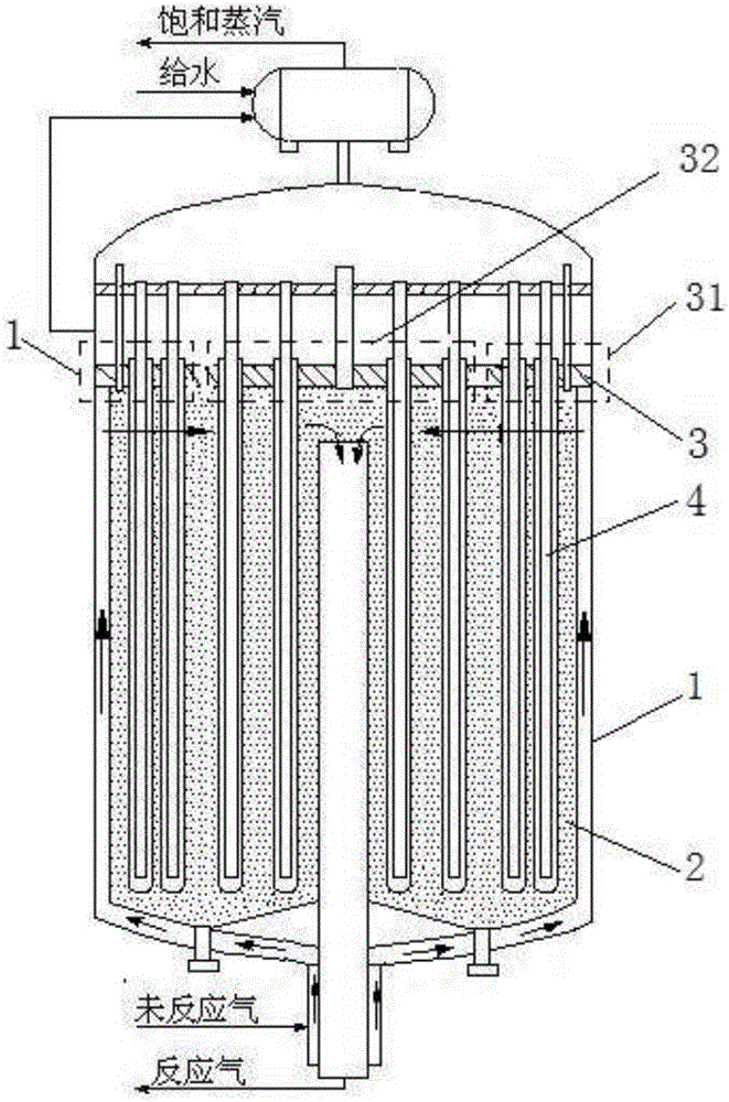
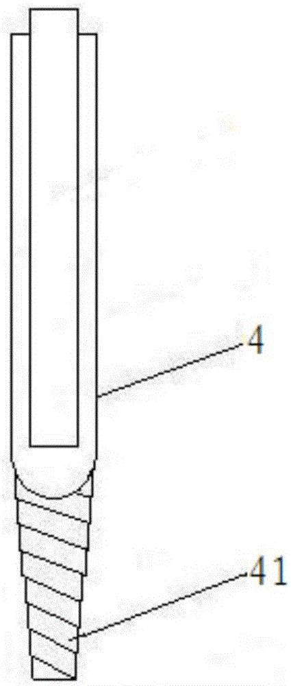
[0029] An isothermal reactor such as figure 1 As shown, it includes a shell 1, a catalyst bed 2, a tube sheet 3 and a heat exchange tube 4. The upper end of the heat exchange tube 4 is installed on the tube sheet 3, and the lower end of the heat exchange tube 4 extends into the catalyst. In the bed layer 2, the tube sheet 3 includes at least two installation areas where the heat exchange tubes 4 are arranged with different densities.

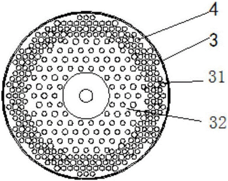
[0030] Such as figure 2 As shown, each installation area is an annular area with the center of the tube plate 3 as the center. figure 2 Among them, there are two installation areas, which are dense area and sparse area respectively, and the arrangement density of the heat exchange tubes 4 in the dense area is higher than that in the sparse area. Such as figure 1 As shown, the reaction gas flows from the inner wall of the isothermal reactor shell to the center of the catalyst bed, the dense area is the ring area 31 near the edge of the tube ...


PUM


Abstract

An isothermal reactor is disclosed. The isothermal reactor comprises a shell, a catalyst bed layer, a tube sheet and heat exchange tubes. The upper ends of the heat exchange tubes are mounted to the tube sheet. The lower ends of the heat exchange tubes penetrate into the catalyst bed layer. The tube sheet comprises at least two mounting zones with different heat exchange tube arranging densities. According to reaction characteristics of reaction gas in the isothermal reactor, the tube sheet is divided into a plurality of the mounting zones, and the mounting zones are provided with different numbers of the heat exchange tubes. The isothermal reactor overcomes a catalyst deactivation problem of isothermal reactors at present, achieves energy conservation and consumption reduction, saves materials of the heat exchange tubes and reduces the equipment cost.

Description

technical field [0001] The invention relates to an isothermal reactor, in particular to the field of coal, petroleum, natural gas and industrial gas treatment, which is used to realize functions such as CO conversion reaction, methanation reaction and sulfur recovery. Background technique [0002] In the field of coal, oil, natural gas and industrial gas processing, there are many strong exothermic reactions, such as CO shift reaction, methanation reaction and direct oxidation reaction for sulfur recovery. [0003] Taking the CO shift reaction as an example, every time 1% of CO is shifted, the temperature rises by 9-10 °C; for the direct oxidation reaction of sulfur recovery, the volume fraction of 1% H 2 The temperature rise caused by the heat of reaction from S to sulfur is 70°C. Therefore, the reaction temperature must be controlled to prevent catalyst deactivation due to over-temperature, or even burnout of the catalyst. In the existing reactors, in order to control the...

Claims


Application Information

Patent Timeline
Patent Type & Authority Applications(China)
IPC IPC(8): B01J8/02C01B3/12C01B17/04
CPCB01J8/0221B01J8/0278B01J8/0285B01J2208/00132B01J2208/00893B01J2208/021B01J2208/027C01B3/12C01B17/04
Inventor 谢定中
Owner HUNAN ANCHUN ADVANCED TECH
Why Eureka
Try Eureka