


Quick Research
Generate reliable direction feasibility study reports for your R&D in just a few steps.

Technical Q&A
Discover and master advanced knowledge NOW. Basics, ideas, possibilities, all at once.

Find Solutions
As an expert in R&D theories, this can generate solutions to your technical problems instantly.

Evaluate Feasibility
Analyze your overall solution with one click, know your potential R&D risks in advance.

Monitor Landscape
Get weekly tech updates, stay abreast of the latest tech innovations and key insights.
An emergency bypass device for a porous ceramic dust collector
A porous ceramic, emergency bypass technology, applied in membrane filters, transportation and packaging, chemical instruments and methods, etc., can solve problems such as porous ceramic clogging system operation, and achieve the effect of avoiding clogging, recycling, and enhancing filtration rate.
- Summary
- Abstract
- Description
- Claims
- Application Information
AI Technical Summary
Problems solved by technology
Method used
Image

Examples
Embodiment 1
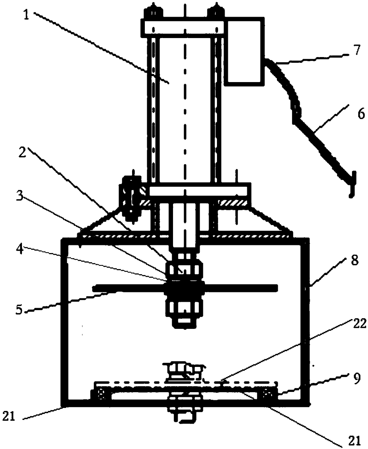
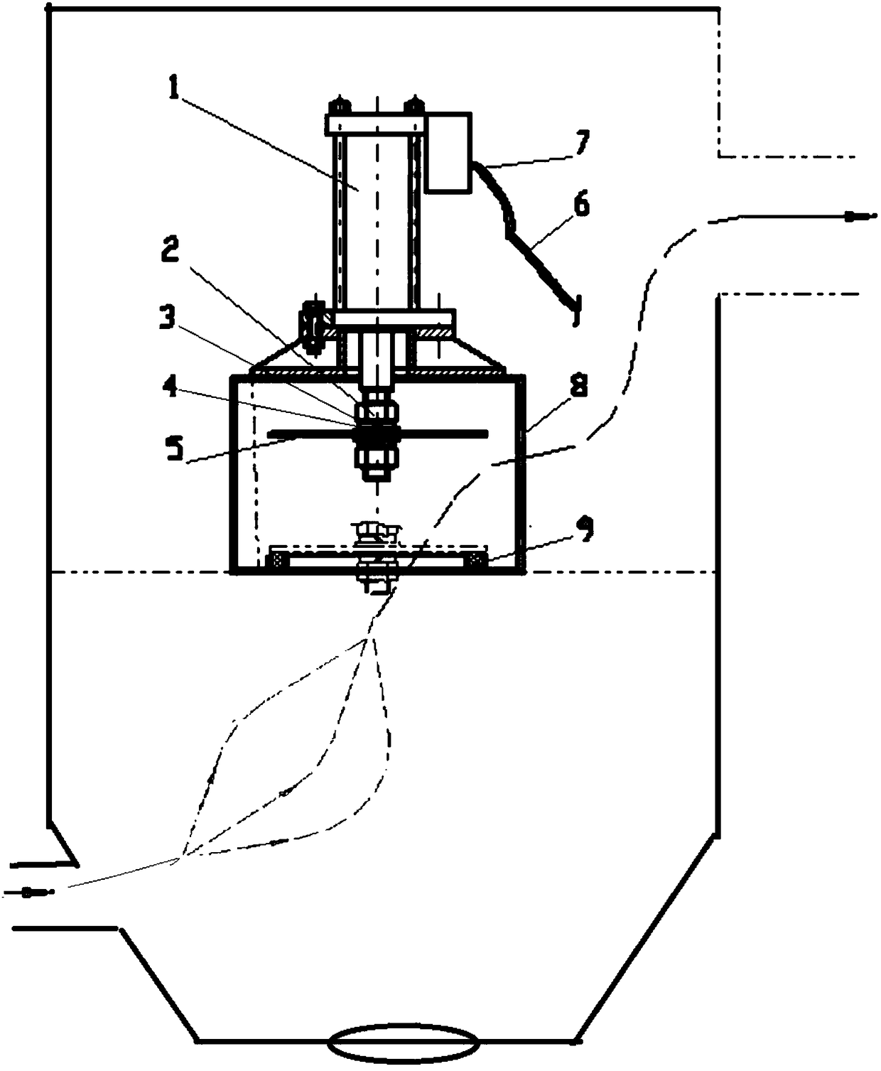
[0015] Example 1: The emergency bypass device of the porous ceramic dust collector is installed inside the porous ceramic dust collector, specifically on the flower plate between the upper box and the lower box, and a circular bypass hole is opened in the middle of the flower plate. The device includes a valved cylinder (1) equipped with a solenoid valve, and a valve plate (5) is arranged at the bottom of the cylinder; the valve plate (5) is fixed by a nut (2), a flat washer (3), and a spring washer (4). Air intake pipe (6) and copper gas nozzle (7) are arranged. The cylinder with valve is installed on the base (8), and there are air holes on both sides of the base (8), and a round graphite pad (9) for sealing is arranged around the partition bypass hole (21). The up and down movement of the valve plate (5) is driven by the expansion and contraction of the valved cylinder (1). When the valve plate (5) stretches and moves downward, it can be closely attached to the graphite pad...
Embodiment 2
[0016] Example 2: The emergency bypass device of the porous ceramic dust collector is installed inside the porous ceramic dust collector, specifically on the flower plate between the upper box and the lower box, and a circular bypass hole is opened in the middle of the flower plate. The device includes a valved cylinder (1) equipped with a solenoid valve, and a valve plate (5) is arranged at the bottom of the cylinder; the valve plate (5) is fixed by a nut (2), a flat washer (3), and a spring washer (4). Air intake pipe (6) and copper gas nozzle (7) are arranged. The cylinder with valve is installed on the base (8), and there are air holes on both sides of the base (8), and a round graphite pad (9) for sealing is arranged around the partition bypass hole (21). The up and down movement of the valve plate (5) is driven by the expansion and contraction of the valved cylinder (1). When the valve plate (5) stretches and moves downward, it can be closely attached to the graphite pad...
PUM
 Abstract
Description
Claims
Application Information
 - R&D Engineer
- R&D Manager
- IP Professional
- Industry Leading Data Capabilities
- Powerful AI technology
- Patent DNA Extraction
Browse by: Latest US Patents, China's latest patents, Technical Efficacy Thesaurus, Application Domain, Technology Topic, Popular Technical Reports.
© 2024 PatSnap. All rights reserved.Legal|Privacy policy|Modern Slavery Act Transparency Statement|Sitemap|About US| Contact US: help@patsnap.com