Optical power composite cable possessing parallel cable cores
A technology for optoelectronic hybrid cables and cable cores, which is applied in the directions of cables, circuits, optics, etc., can solve the problems of difficult separation of electrical units and optical units, high cost of composite cables, and non-compact structure. , compact structure
- Summary
- Abstract
- Description
- Claims
- Application Information
AI Technical Summary
Problems solved by technology
Method used
Image

Examples
Embodiment 1
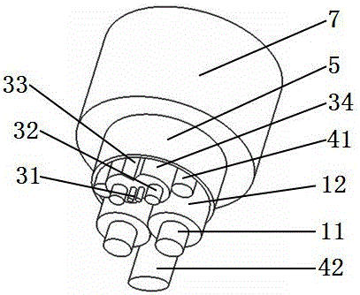
[0030] Please see figure 1 with figure 2 , A photoelectric hybrid cable with parallel cable cores, which includes a cable core, a first protective layer 5 located outside the cable core, and an outer sheath 7 located outside the first protective layer; characterized in that the cable core is insulated by two A wire, a butterfly-shaped optical cable, two round filling ropes 41, and an oval-shaped filling rope 42; each insulated wire is composed of a conductor 11 and an insulating layer 12 covering the conductor; the butterfly-shaped optical cable consists of two The light unit 31, two reinforcements 32 located on the horizontal sides of the light unit, and a unit sheath 34 covering the light unit and the reinforcements are formed. There are two tear openings 33 on the unit sheath. The openings are located on both vertical sides of the optical unit, any cross section: the intersection of the line between the tops of the two tear openings and the line between the centers of the tw...
Embodiment 2
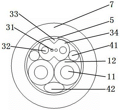
[0032] Please see image 3 with Figure 4 , A photoelectric hybrid cable with parallel cable cores, which includes a cable core, a first protective layer 5 located outside the cable core, and an outer sheath 7 located outside the first protective layer; characterized in that the cable core is insulated by two A wire, a butterfly-shaped optical cable, two round filling ropes 41, and an oval-shaped filling rope 42; each insulated wire is composed of a conductor 11 and an insulating layer 12 covering the conductor; the butterfly-shaped optical cable consists of two The light unit 31, two reinforcements 32 located on the horizontal sides of the light unit, and a unit sheath 34 covering the light unit and the reinforcements are formed. There are two tear openings 33 on the unit sheath. The openings are located on both vertical sides of the optical unit, any cross section: the intersection of the line between the tops of the two tear openings and the line between the centers of the tw...
Embodiment 3
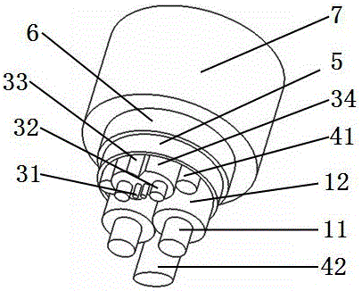
[0034] Please see Figure 5 And refer to Figure 1 to Figure 4 , A photoelectric hybrid cable with parallel cable cores, which includes a cable core, a first protective layer 5 located outside the cable core, and an outer sheath 7 located outside the first protective layer; characterized in that the cable core is insulated by two Wire, a butterfly-shaped optical cable, two round filling ropes 41, and an oval-shaped filling rope 42; each insulated wire is composed of a conductor 11 and an insulating layer 12 covering the conductor; the butterfly-shaped optical cable is composed of a light The unit 31, two reinforcing members 32 located on the horizontal sides of the light unit, and a unit sheath 34 covering the light unit and the reinforcing members are formed, and the unit sheath has two tear openings 33, two tear openings Located on both vertical sides of the optical unit, on either cross-section: the point where the line between the tops of the two tear openings and the line ...
PUM
 Abstract
Description
Claims
Application Information
 - R&D
- Intellectual Property
- Life Sciences
- Materials
- Tech Scout
- Unparalleled Data Quality
- Higher Quality Content
- 60% Fewer Hallucinations
Browse by: Latest US Patents, China's latest patents, Technical Efficacy Thesaurus, Application Domain, Technology Topic, Popular Technical Reports.
© 2025 PatSnap. All rights reserved.Legal|Privacy policy|Modern Slavery Act Transparency Statement|Sitemap|About US| Contact US: help@patsnap.com