Material taking device
A technology of a reclaiming device and a grasping device, which is applied in the directions of transportation and packaging, conveyor objects, etc., can solve the problems of the complex movement mechanism of the grasping device, and achieve the effects of small size, improved work efficiency, and reduced volume.
- Summary
- Abstract
- Description
- Claims
- Application Information
AI Technical Summary
Problems solved by technology
Method used
Image
Examples
Embodiment 1
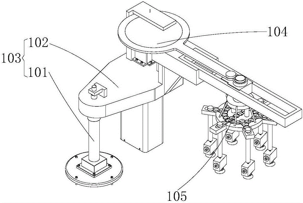
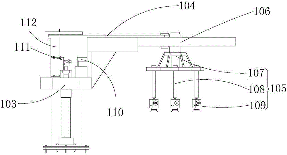
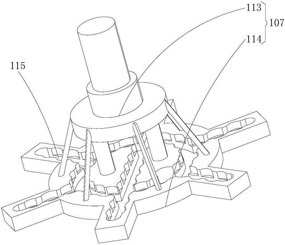
[0045] refer to Figure 1 to Figure 5 , the present embodiment provides a retrieving device, including a base 103, a grabbing device 105 and a driving device, the driving device includes a driving mechanism and a crank slider 121 mechanism 104, the driving mechanism is installed on the base 103, and the output end of the driving mechanism The input end of the slider crank 121 mechanism 104 is driven and connected, and the output end of the slider crank 121 mechanism 104 is connected with the grasping device 105, and the slider crank 121 mechanism 104 makes the grasping device 105 reciprocate.
[0046] When the existing retrieving device realizes the reciprocating movement of the grabbing device 105, a guide rail is generally provided, and then the grabbing device 105 is slid back and forth along the guide rail. The whole becomes bulky and complicated. The retrieving device provided in this embodiment adopts the crank slider 121 mechanism 104 instead of the guide rail mechanis...
Embodiment 2
[0060] This embodiment also provides a material retrieving device. This embodiment is a further transformation based on the technical solution of Embodiment 1. The technical solution described in Embodiment 1 is also applicable to this embodiment. The technical solution will not be described repeatedly.
[0061] Specifically, the difference between this embodiment and Embodiment 1 is that the output end of the driving device of the reclaiming device provided by this embodiment is connected to the center of the rotating part 118, and a bump is provided at the eccentric position of the rotating part 118, and the connecting rod 120 is rotationally connected with the projection, and the projection rotates relative to the connecting rod 120 along the axis of the rotating portion 118 . This method is more common, and it is more convenient and quicker to implement, but the slider crank 121 mechanism 104 in the first embodiment is smaller in size and more dexterous in operation.
PUM
 Abstract
Description
Claims
Application Information
 - R&D
- Intellectual Property
- Life Sciences
- Materials
- Tech Scout
- Unparalleled Data Quality
- Higher Quality Content
- 60% Fewer Hallucinations
Browse by: Latest US Patents, China's latest patents, Technical Efficacy Thesaurus, Application Domain, Technology Topic, Popular Technical Reports.
© 2025 PatSnap. All rights reserved.Legal|Privacy policy|Modern Slavery Act Transparency Statement|Sitemap|About US| Contact US: help@patsnap.com


