Wind Power Generator

A technology for wind turbines and generators, which is applied in the directions of wind turbines, wind turbine combinations, and wind power generation, and can solve problems such as being unsuitable for wind power generation.

Inactive Publication Date: 2016-08-03
ABB (SCHWEIZ) AG
View PDF8 Cites 0 Cited by
  • Summary
  • Abstract
  • Description
  • Claims
  • Application Information

AI Technical Summary

Problems solved by technology

However, the above example is not suitable for wind power applications due to the problematic cooling of the superconducting coils

Method used


Image

  • Wind Power Generator
  • Wind Power Generator
  • Wind Power Generator

Examples


Embodiment Construction

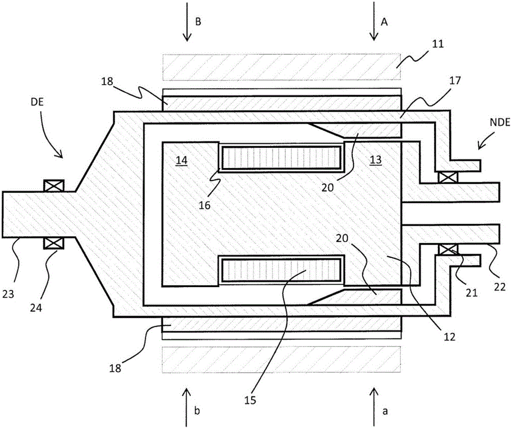
[0018] figure 1 A cross-sectional view of a wind power generator according to an embodiment of the present invention is shown. The generator is cut in half in the longitudinal direction which is the direction of the axis of the generator. figure 1 The stator 11 of the generator is shown, which is the outermost part of the generator. The stator is equipped with stator windings. The stator windings of the generator of the present disclosure may be of any known type of winding. Usually, the stator winding is a multi-phase winding, preferably a three-phase winding. Since the rotor structure of the wind generator of the invention forms magnetic poles comparable to permanently magnetized magnetic poles, the stator windings can have the design normally used in conjunction with synchronous generators. More specifically, the stator winding is formed in the stator core such that the axial length of the stator winding corresponds to the length of the stator core. The stator windings...


PUM


Abstract

A wind power generator comprising a stator, a rotor with a shaft connectable to wind turbine and a stationary superconducting coil structure for magnetizing the rotor of the wind power generator, the stator of the wind power generator comprising a multi-phase winding for producing electricity from the wind power generator. The wind power generator is a synchronous generator, and the superconducting coil structure comprises end portions that are arranged to be magnetized with opposing polarities by a superconducting coil, and the rotor comprises poles ex-tending in the surface of the rotor in the direction of the shaft of the generator, the poles being arranged to be magnetized using the superconducting coil structure, wherein each rotor pole is arranged to extend inwardly at one end of the pole such that the inwardly extended end of the pole is arranged in the vicinity of an end portion of the superconducting coil structure for magnetizing the rotor pole and wherein the rotor poles comprises pole shoes, which are formed to provide sinusoidally varying air gap flux in the air gap between stator and rotor.

Description

technical field [0001] The present invention relates to wind power generators, and more particularly to wind power generators employing superconductors to provide rotor magnetization. Background technique [0002] The use of superconducting wires to generate excitation on rotating electrical machines is known in the field of rotating electrical machines. [0003] An example of a structure using a superconducting coil to magnetize a rotor is proposed in JP55005043A. In this document, superconducting coils surround an induction core forming the rotor structure. When direct current is supplied to the coil, the induction core is magnetized so that salient poles are formed at both ends of the induction core. The stator of the electric machine includes corresponding magnetic poles at both ends of the inner structure of the stator. The ends of the stator are supplied with alternating current to obtain the force to drive the motor. Alternatively, generating a voltage in both end...

Claims


Application Information

Patent Timeline
Patent Type & Authority Applications(China)
IPC IPC(8): H02K55/02H02K7/18H02K19/24H02K1/24
CPCH02K19/24H02K55/02H02K1/24H02K7/1838Y02E10/72Y02E40/60F03D9/25H02K1/12H02K7/085H02K7/183H02K19/16
Inventor 埃诺·西兰德
Owner ABB (SCHWEIZ) AG
Why Eureka
Try Eureka