sanitary pool

A sanitary pool, sanitary technology, applied in the field of sanitary pools, can solve problems such as coating enamel damage, cover appearance and durability damage

Inactive Publication Date: 2015-08-19
FRANZ KALDEWEI GMBH & CO KG
View PDF6 Cites 0 Cited by
  • Summary
  • Abstract
  • Description
  • Claims
  • Application Information

AI Technical Summary

Problems solved by technology

Especially at the edge of the sheet metal there is the danger that the coating, such as the enamel, will be damaged under strong mechanical loads, for example if the cover is dropped
At least in such cases when complete protection is no longer provided by the enamel, the thin-walled cover can be oxidized in exposed places, whereby the appearance and durability of the cover is compromised

Method used


Image

  • sanitary pool
  • sanitary pool
  • sanitary pool

Examples


Embodiment Construction

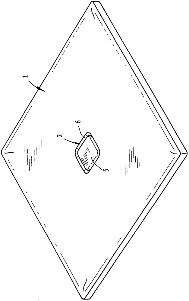
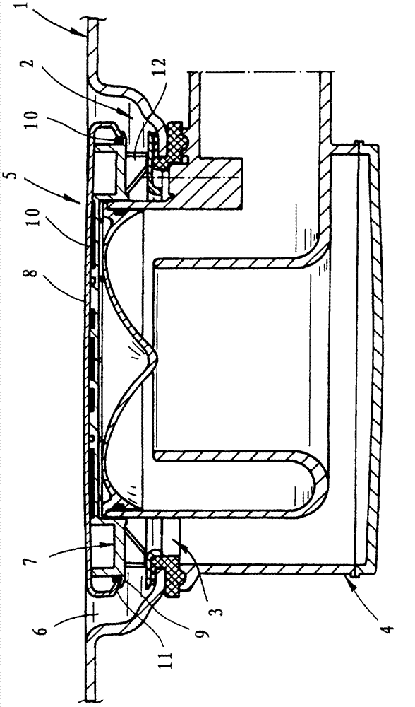
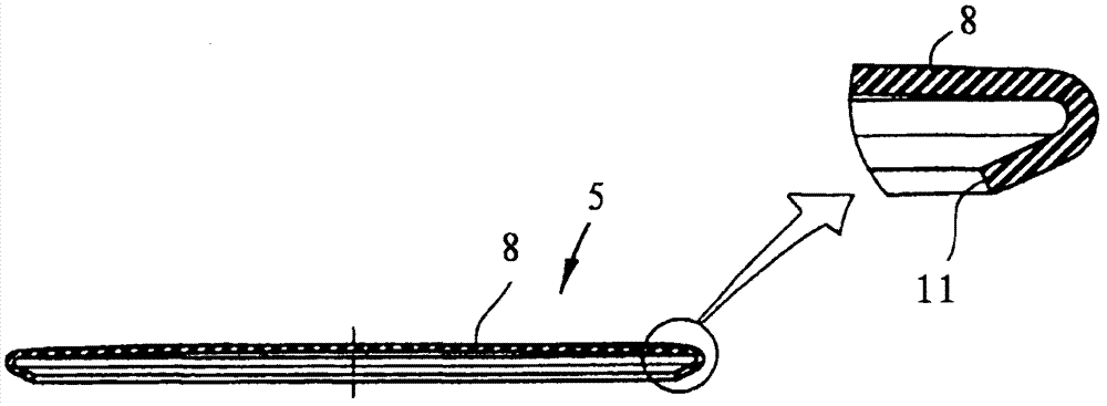
[0036] figure 1 A flat shower basin is shown by way of example with a basin bottom 1 having a drain hole 3 in a recess 2 with a drain assembly 4 connected on the underside to the drain hole 3 . exist figure 1 , the drain hole 3 including the drain assembly 4 is covered by a metal element 5 made of enamelled sheet metal arranged above them, the metal element 5 having a shape that fits into the recess 2 and between the metal element 5 and the pool bottom 1 A gap 6 for water drainage remains in between.

[0037] as in particular from figure 2 It can also be seen that the metal element 5 as a visible cover is preferably flush with the surface of the region of the tank bottom 1 adjoining the recess 2 , so that apart from the gap 6 there is a continuous surface. The metal element 5 is generally slightly bent in the direction of the edge of the metal element to ensure water drainage. However, this slight curvature is barely perceptible.

[0038] figure 2 shown in section fig...


PUM


Abstract

The sanitary tub has a discharge opening (3) that is arranged in a recess (2) at a tub base (1). A drain set (4) is attached on the lower side to the discharge opening. A metal element (5) made of coated or non-coated layer is arranged over the discharge opening. The metal element has a shape suitable to the recess, and a gap (6) is formed between the metal element and the tub base for the water discharge. The base area is covered by the metal element.

Description

technical field [0001] The invention relates to a sanitary basin having a drain hole provided in a recess in the bottom of the pool, a drain assembly connected to the drain hole on the underside, and a coated or uncoated A metal element made of sheet metal having a shape to fit the recess and leaving a gap between the metal element and the bottom of the pool for water to drain. Background technique [0002] The metal element forms the user-visible cover of the drain and can be accommodated in the recess due to its matching shape, so that the metal element preferably protrudes only slightly from the area of ​​the basin floor adjoining the recess. It is particularly preferred that the metal element as the uppermost covering of the drain is flush with the surface of the region of the basin bottom that adjoins the recess. [0003] The drain is optimally integrated into the basin floor by the insertion of the metal element into the recess and preferably flush with the surface of...

Claims


Application Information

Patent Timeline
Patent Type & Authority Patents(China)
IPC IPC(8): E03C1/22A47K3/40
CPCE03F5/0408E03C1/29A47K1/14A47K3/02A47K3/40E03F2005/0418F16D13/757E03C1/264
Inventor B·韦斯特L·马泰纳
Owner FRANZ KALDEWEI GMBH & CO KG
Why Eureka
Try Eureka