Offset printer

A technology of offset printing and printing plates, which is applied in the field of offset printing devices, can solve problems such as lowering printing quality, achieve the effects of increasing yield, reducing manufacturing costs, and preventing printing accuracy from decreasing

Active Publication Date: 2013-09-11
TOPPAN PRINTING CO LTD
View PDF9 Cites 0 Cited by
  • Summary
  • Abstract
  • Description
  • Claims
  • Application Information

AI Technical Summary

Problems solved by technology

[0006] However, in recent years, ultra-fine pattern formation accuracy has been demanded, and even with the above-mentioned offset printing method, when forming a fine pattern pattern, especially a pattern formed by combining straight lines, the printing quality may deteriorate.
Such a problem is a major one that cannot be ignored

Method used


Image

  • Offset printer
  • Offset printer
  • Offset printer

Examples


Embodiment Construction

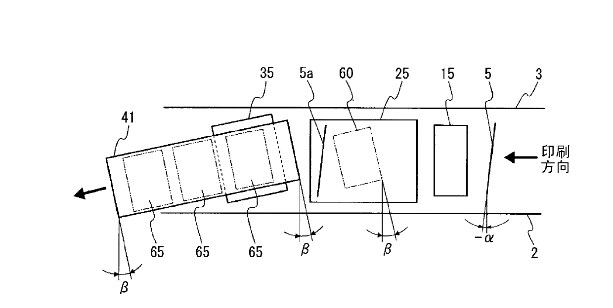
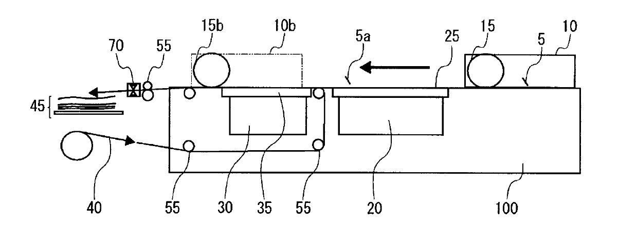
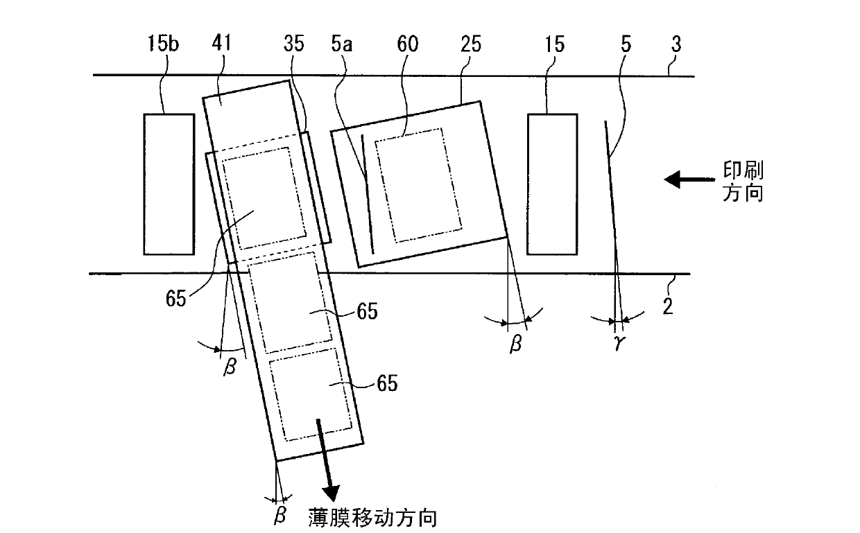
[0040] Next, preferred embodiments of the fine pattern printing apparatus of the present invention will be described with reference to the drawings. Figure 1A And 1B shows the first embodiment of the fine pattern printing device of the present invention. Figure 1A is a top view, Figure 1B are side views, and they show the schematic structure of the device. In addition, the same code|symbol is attached|subjected to the same member as the conventional offset printing apparatus 1 shown in FIG. 3, and description is abbreviate|omitted.

[0041]The fine-pattern printing apparatus 100 according to the first embodiment of the present invention is an offset printing apparatus, and as shown in the figure, the doctor blade 5 is installed obliquely with respect to the printing direction indicated by the arrow in plan view. The attachment angle -α of the squeegee 5 is an angle inclined clockwise with respect to a line perpendicular to the printing direction (a fourth inclination angl...


PUM


Abstract

An offset printer is characterized by being provided with a doctor blade, a blanket roll, a plate mounting surface plate, a printing plate disposed on the plate mounting surface plate, and a printing surface plate, and characterized in that the printing plate is disposed to be inclined at a first inclination angle with respect to a printing advance direction, the printing surface plate is disposed to be inclined at a second inclination angle with respect to the printing advance direction, the doctor blade is disposed so as not to be parallel to the printing plate, and an object to be printed is supplied in the direction inclined at a third inclination angle with respect to the printing advance direction such that patterns are printed parallel to a part to be printed.

Description

technical field [0001] The present invention relates to an offset printing apparatus capable of printing circuit wiring patterns, etc., and fine patterns in various devices related to semiconductors, etc., with high precision. [0002] This application claims priority based on Japanese Patent Application No. 2011-035290 filed on February 22, 2011, and uses the content thereof. Background technique [0003] Circuit wiring patterns and the like and electrode patterns in various devices related to semiconductors need to be formed with extremely high precision. Conventionally, such high-precision electrode patterns and the like have been formed by photolithography. However, there are problems in that the process of photolithography is complicated, and an exposure device is required for pattern formation, and material loss is large, which leads to a decrease in productivity and an increase in manufacturing cost. [0004] In addition, a screen printing method is known as another...

Claims


Application Information

Patent Timeline
Patent Type & Authority Applications(China)
IPC IPC(8): B41F3/38B41F3/20B41F17/14
CPCB41F3/20B41F3/38B41F3/46B41F17/14
Inventor 中屋芳纪上奥伸司
Owner TOPPAN PRINTING CO LTD
Why Eureka
Try Eureka