
Hydraulic system for driving a vibratory mechanism

一种液压系统、振动机构的技术,应用在液压系统领域,达到提高燃料效率的效果

Active Publication Date: 2016-08-03
VOLVO CONSTR EQUIP AB
View PDF5 Cites 11 Cited by
  • Summary
  • Abstract
  • Description
  • Claims
  • Application Information

AI Technical Summary

Problems solved by technology

However, there is still room for improvement relative to the fuel efficiency and cost effectiveness of compactors

Method used


Image

  • Hydraulic system for driving a vibratory mechanism
  • Hydraulic system for driving a vibratory mechanism
  • Hydraulic system for driving a vibratory mechanism

Examples


Embodiment Construction

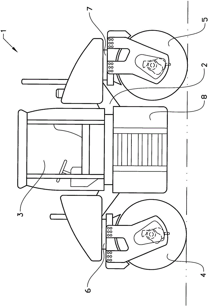
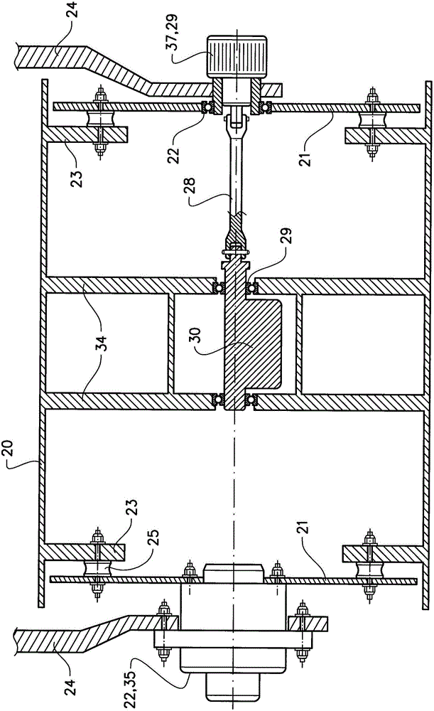
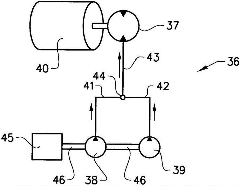
[0035] In the following, various aspects of the disclosure will be described to illustrate (but not limit) the disclosure, taken in conjunction with the accompanying drawings, wherein like numerals refer to like elements, and variations of the described aspects are not limited to the particular illustrated embodiments, but rather Other variations of the present disclosure can be applied.

[0036] Steel vibrating rollers and drums apply force which enhances compaction. The vibrating roll has an internal eccentric weight that rotates on an axis. This rotating eccentric weight causes the roller to move in all directions, but an active part of it is up and down. Vibratory forces are the rapid up and down motions that cause concrete aggregates and soil particles to move. Aggregate in motion tends to reorient itself more easily so the material compacts more easily under the weight of the rollers. Vibration is a particularly effective means for aggregate or granular materials like...


PUM


Abstract

The disclosure concerns a hydraulic system (36) for driving a vibratory mechanism (40) of a compaction roller (4, 5). The hydraulic system (36) comprising at least one hydraulic motor (37) connectable to vibratory mechanism (40) and a first hydraulic pump (38) fluidly connected to the at least one hydraulic motor (37) and arranged for supplying pressurised hydraulic fluid to the at least one hydraulic motor (37). The hydraulic system (36) further comprises a second hydraulic pump (39) fluidly connected to the at least one hydraulic motor (37) and arranged for supplying pressurised hydraulic fluid to the at least one hydraulic motor (37). The disclosure also concerns a corresponding method for controlling a vibratory mechanism (40) of a compaction roller.

Description

technical field [0001] The present disclosure relates to a hydraulic system for driving a vibration mechanism of a compaction roll. The hydraulic system includes at least one hydraulic motor connectable to the vibrating mechanism; and a hydraulic pump fluidly connected to the at least one hydraulic motor and arranged to pump pressurized hydraulic fluid supplied to the at least one hydraulic motor. The present disclosure also relates to a corresponding method for controlling an oscillating mechanism of a compacting roller. The hydraulic system can be mounted on a compactor comprising a single, two or more compaction rollers. Background technique [0002] Compactors are used especially in earthworks and road construction to compact the ground on a work site to achieve a smooth and level ground. Ground may include soil, gravel, asphalt, etc. The compactor includes at least one generally cylindrical compacting roller that compresses the soil flat. A compactor relies in part...

Claims


Application Information

Patent Timeline
Patent Type & Authority Applications(China)
IPC IPC(8): E01C19/28
CPCE01C19/286F15B2211/2654F15B1/024E01C19/28E01C19/282F15B1/04F15B11/17F15B21/02F15B2211/20538F15B2211/20546F15B2211/20576F15B2211/75
Inventor 罗兰德·维克托埃里克·古斯塔夫·利耶比约恩
Owner VOLVO CONSTR EQUIP AB
Learn More