A tuyere structure and manufacturing method thereof

A technology of tuyere and ventilation duct, which is applied in the field of vents, which can solve the problems of not being able to fit each other, the sealing effect, dust entering the room, and the louver blades being easily blown, etc., to achieve the effect of firm welding effect, increased efficiency, and convenient operation

Active Publication Date: 2018-11-09
SUZHOU VENTILATION EQUIP CO LTD
View PDF8 Cites 0 Cited by
  • Summary
  • Abstract
  • Description
  • Claims
  • Application Information

AI Technical Summary

Problems solved by technology

[0004] The existing vent structure fails in the ventilation duct. When the smoke is discharged to the outside, the ventilation duct needs to be closed through the vent structure to prevent the smoke from entering the room from the ventilation duct and affecting people's health. However, After the existing air vent structure closes the ventilation duct through the louvers, the louvers are easily blown by the airflow in the duct and cause self-rotation, resulting in a certain gap between two adjacent louvers that cannot interact with each other. The fit achieves a better sealing effect, and dust can easily enter the room from the gap, affecting people's health

Method used


Image

  • A tuyere structure and manufacturing method thereof
  • A tuyere structure and manufacturing method thereof
  • A tuyere structure and manufacturing method thereof

Examples


Embodiment 1

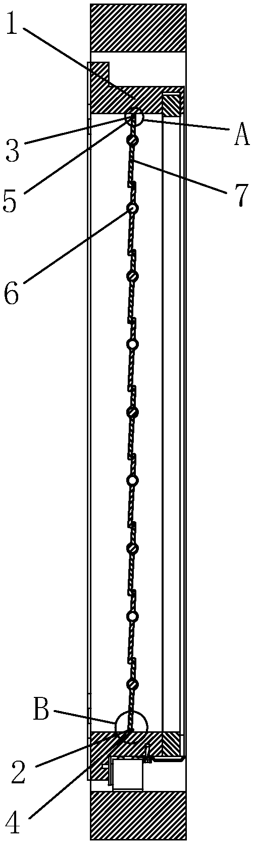
[0034] Embodiment 1: A tuyere structure, refer to Figure 4 , including a frame body 1 arranged around the ventilation duct, the shape of the frame body 1 is a cuboid, a plurality of louver blades 7 are arranged and distributed in the frame body 1 in its length direction, and a plurality of rotating shafts are arranged in the width direction of the frame body 1 6. The two ends of the rotating shaft 6 are rotationally connected with the frame body 1. Each rotating shaft 6 is correspondingly equipped with a louver 7. When the rotating shaft 6 is rotated, the louver 7 rotates around the rotating shaft 6. After the rotation of a plurality of louvers 7, the Ventilation ducts are closed or open;

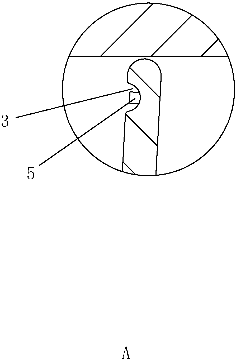
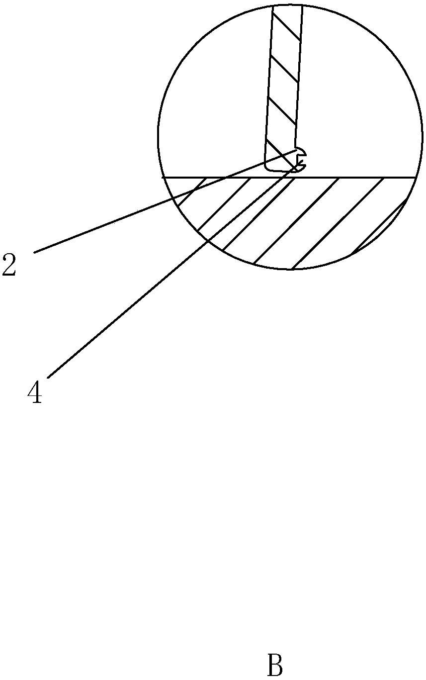
[0035] refer to Figure 1 to Figure 4, the upper side of each louver 7 is provided with a concave groove 3, the concave groove 3 is formed inwardly from the outer surface of the louver 7, and the lower side is provided with a raised strip 2, and the raised strip 2 is formed from the inner...

Embodiment 2

[0040] Embodiment 2: A kind of tuyere structure, refer to Figure 6 The difference from Embodiment 1 is that a rotation button 12 for driving one of the rotating shafts 6 to rotate itself is provided on the side wall of the frame body 1, and it works instead of the driving part 8. The staff drives the rotating shaft 6 to rotate by rotating the rotating button 12. The rotating shaft 6 drives other rotating shafts 6 to rotate synchronously through the transmission belt 9, thereby driving all the louver blades 7 to automatically rotate. The rotation of the louver blades 7 is controlled manually, and the failure rate is low and safe and stable.

Embodiment 3

[0041] Embodiment 3: A manufacturing method applied to the manufacture of the tuyere structure in Embodiment 1 and Embodiment 2 above. The frame body 1 is welded end-to-end by four profiles. Before welding, each profile is cut by a laser cutting process. Cut from the end to the end, remove the waste, and then connect the four profiles end to end, and weld them together by welding to form a rectangular parallelepiped frame 1. The end of the profile cut by the laser cutting process is relatively flat, without many burrs , when performing end-to-end welding with any two of the other three, the gap generated at the welding place is smaller, so that the contact area between the two profiles is larger during welding, and the welding effect achieved is more firm and stable.


PUM


Abstract

The invention discloses an air port structure and a manufacturing method thereof. The air port structure comprises a frame body arranged around an air conduit, a plurality of louver blades are distributed on the frame body in the length direction of the frame body, a sunken groove is formed in the upper side of each louver blade, a protruding strip is arranged on the lower side of each louver blade and is matched with the sunken groove in the adjacent louver blade in a clamped connection mode, the sealing effect of the louver blades is improved, and therefore the sealing effect of the air port is improved, and dust is prevented from entering a room. The end of sectional material cut through the laser cutting technology is smooth and free of too many burrs, gaps generated in welding are small, the contact area between two pieces of sectional material is larger, and therefore the welding effect is firmer and more stable.

Description

technical field [0001] The present invention relates to the technical field of vents, and more specifically, it relates to a vent structure and a manufacturing method thereof. Background technique [0002] At present, in buildings, a central ventilation system will be installed to achieve the function of air intake or exhaust. The central ventilation system includes ventilation ducts and vents. Most of the existing vents on the market are rectangular ones. frame, deflector vanes and coarse-effect filter screen, in a Chinese patent document with the patent application number "201120124446.7", a gear-type tuyere is recorded, which consists of an outer frame, an inner frame, a guide vane, a transmission gear, It is composed of adjusting wheel, lock nut, hinge, spring touch bead, and coarse-effect filter. The outer frame and inner frame are connected by hinge and spring touch bead. The inner frame is turned out from the outer frame through the hinge, and the coarse-effect filte...

Claims


Application Information

Patent Timeline
Patent Type & Authority Patents(China)
IPC IPC(8): F24F13/15
CPCF24F13/1406F24F13/1426F24F13/15F24F2013/1446
Inventor 余和富
Owner SUZHOU VENTILATION EQUIP CO LTD
Why Eureka
Try Eureka