Motor with magnetic-sensing balance sheet
A magnetic balance and motor technology, applied in the field of motors, can solve the problems of insufficient rotation balance structure and no magnetic induction part, so as to ensure the rotation efficiency, avoid shaking, and improve the starting stability.
- Summary
- Abstract
- Description
- Claims
- Application Information
AI Technical Summary
Problems solved by technology
Method used
Image

Examples
Embodiment 1
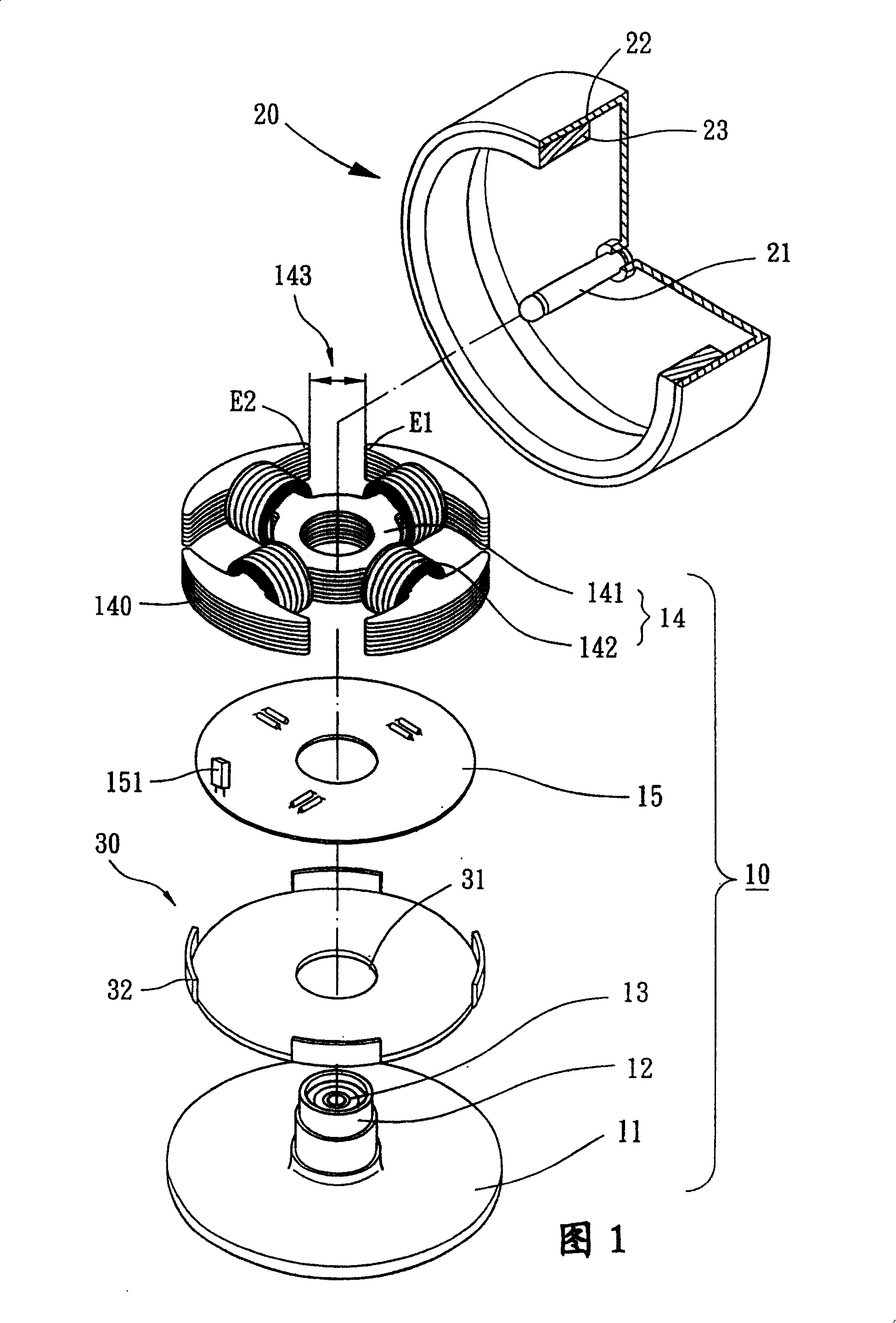
[0052] As shown in FIG. 1 , the present invention includes a fixing part 10 , a rotor 20 and a magnetically sensitive balance piece 30 , and the present invention can be applied to the fields of high-tech motors such as cooling fans or optical disk drive spindle motors.
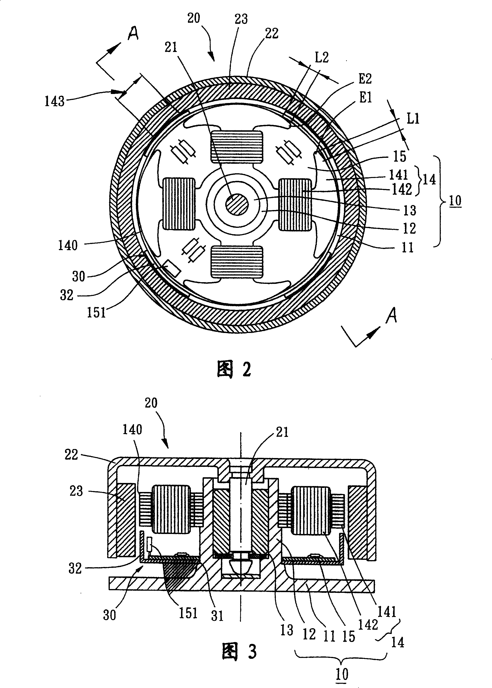
[0053] As shown in Figure 1, Figure 2 and Figure 3, the fixed part 10 includes a base 11 combined with the motor housing, a shaft tube 12, at least one bearing 13 accommodated inside the shaft tube 12, a stator group 14 and a circuit board 15 .
[0054]The shaft tube 12 can be separately manufactured and assembled on the base 11 or directly integrally formed on the base 11 .
[0055] The circuit board 15 and the stator assembly 14 are sheathed on the outer periphery of the shaft tube 12 .
[0056] The bearing 13 can be selected from known bearings such as oil-impregnated bearings, ball bearings, fluid dynamic bearings or magnetic bearings.
[0057] The stator assembly 14 can be selected as a radial winding ...
Embodiment 2
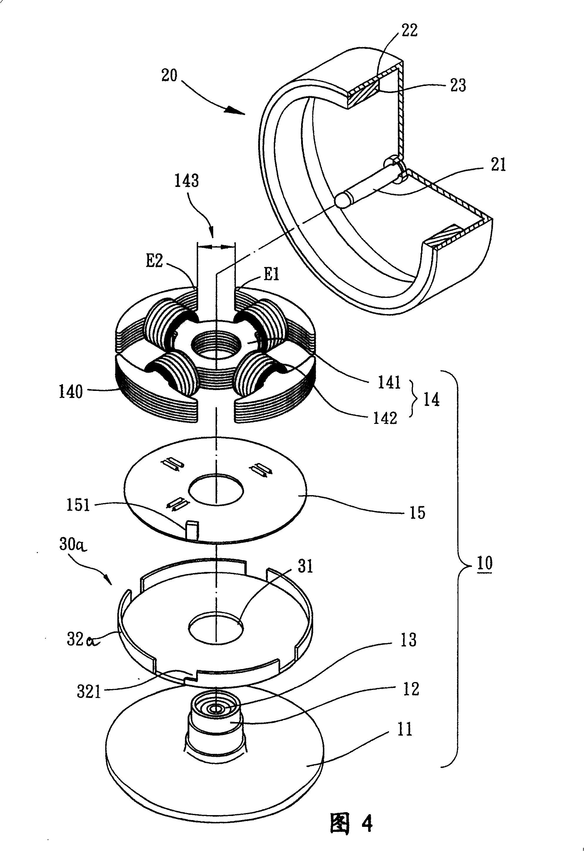
[0068] As shown in Fig. 4, Fig. 5 and Fig. 6, compared with Embodiment 1, the magnetically sensitive balancing sheet 30a of the present invention can also be formed by extending axially from the outer peripheral edge to form at least two magnetically sensitive surfaces 32a, and the magnetically sensitive surfaces 32a are also opposite to each other. It is located at each pole gap 143 of the stator set 14 and faces the inner peripheral surface of the ring magnet 23 of the rotor 20 at the same time. Furthermore, the span of the magnetic sensing surface 32 a is greater than the length of the pole gap 143 , and the magnetic sensing surface 32 a and two adjacent magnetic pole surfaces 140 have two overlapping lengths L1 , L2 of unequal length. Wherein, at least one overlapping length L1 is preferably less than 1 / 2, especially 1 / 3, of the total length of the magnetic pole surface 140 . At the same time, another overlapping length L2 can be selected to be greater than 1 / 2 of the tota...
Embodiment 3
[0070] As shown in Fig. 7, Fig. 8 and Fig. 9, compared with Embodiment 1, the magnetically sensitive balancing sheet 30b of the present invention forms several notches 33 corresponding to the magnetic pole faces 140 of the stator group 14, and simultaneously forms the pole gaps 143 corresponding to the stator group 14 There are several extension parts 34, and several magnetically sensitive surfaces 32b are directly formed on the upper surface of the end part of the extension part 34. The magnetically sensitive balancing sheet 30 b can also be selectively attached to the lower surface or the upper surface of the circuit board 15 . During assembly, the magnetically sensitive surface 32 b is preferably located at the position of each pole gap 143 of the stator assembly 14 , and faces the bottom surface of the ring magnet 23 of the rotor 20 at the same time. Furthermore, the magnetically sensitive surface 32b of the extension portion 34 is not less than the length of the pole gap ...
PUM
 Abstract
Description
Claims
Application Information
 - R&D
- Intellectual Property
- Life Sciences
- Materials
- Tech Scout
- Unparalleled Data Quality
- Higher Quality Content
- 60% Fewer Hallucinations
Browse by: Latest US Patents, China's latest patents, Technical Efficacy Thesaurus, Application Domain, Technology Topic, Popular Technical Reports.
© 2025 PatSnap. All rights reserved.Legal|Privacy policy|Modern Slavery Act Transparency Statement|Sitemap|About US| Contact US: help@patsnap.com