Processing device of shielding layer at end part of shielding cable
An end shielding and processing device technology is applied in the field of shielded cable processing devices, which can solve the problem of long time consumption, and achieve the effects of short pulling and breaking time, improving processing efficiency and high efficiency.
- Summary
- Abstract
- Description
- Claims
- Application Information
AI Technical Summary
Problems solved by technology
Method used
Image
Examples
Embodiment 1
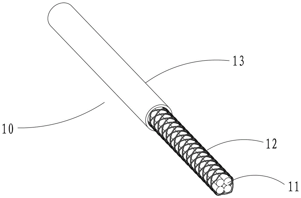
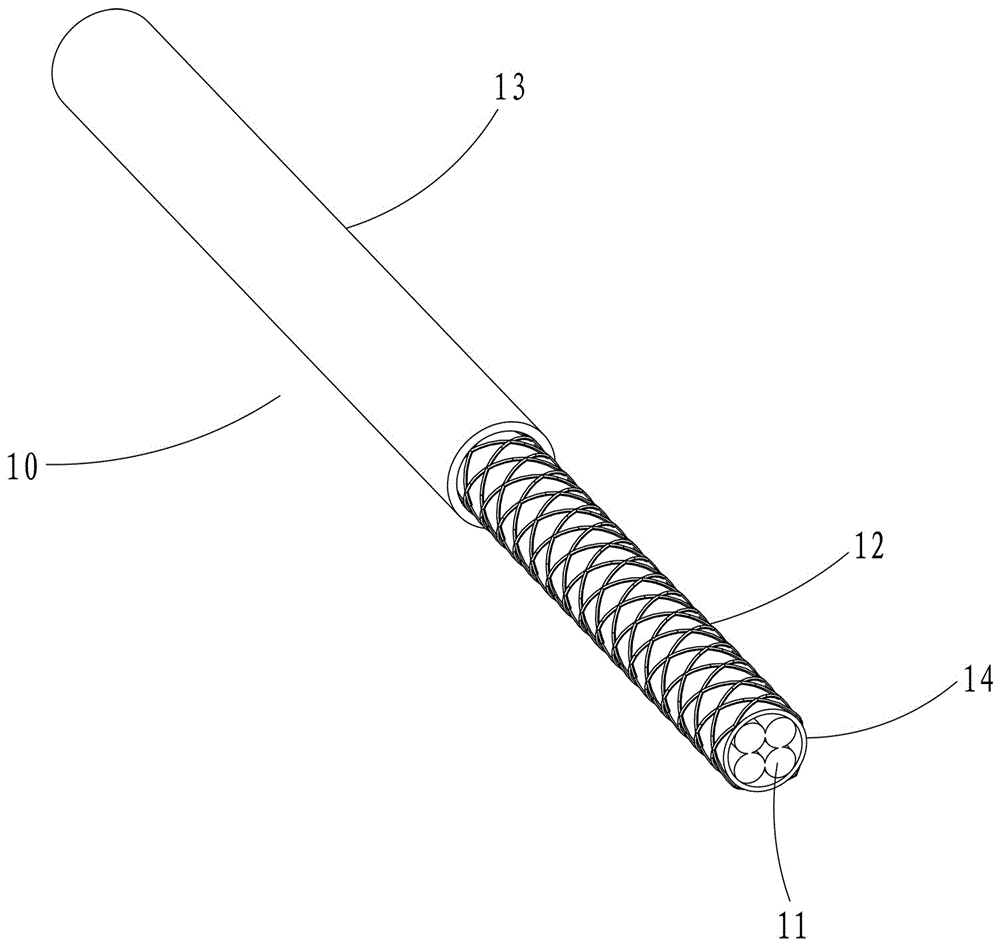
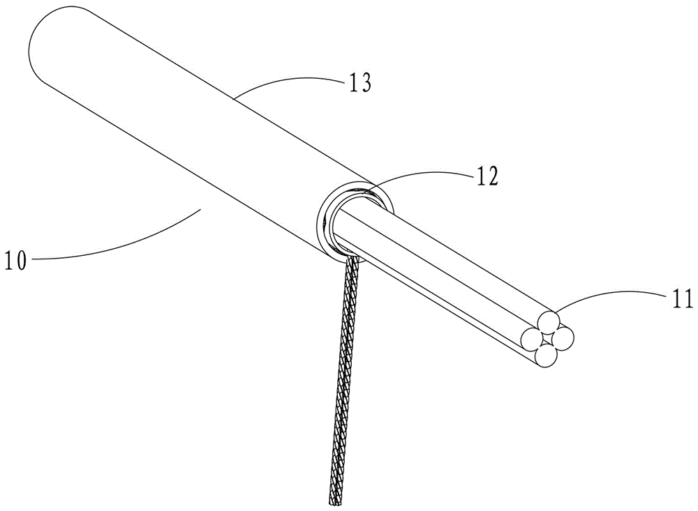
[0034] see Figure 4 , 5 The device for processing the shielding layer at the end of a shielded cable in the present invention includes a carding needle piercing assembly 41 at the front and a pulling and stripping movement mechanism 42 at the rear. The needle point 4111 of the carding needle 411 in the carding needle insertion assembly 41 can be inserted into the metal wire braided shielding layer 12 or the aluminum foil shielding layer 14 from the entire circumferential direction. The pulling and stripping movement mechanism 42 can drive the carding needle insertion assembly 41 to move backward, and use the carding needle 411 inserted into the metal wire braided shielding layer 12 to comb the braided metal wires into a loose shape, or use the carding needle 411 inserted into the aluminum foil The carding needle 411 in the shielding layer 14 peels off the aluminum foil shielding layer 14 .
[0035] see Figure 6 , 7 , the carding needle piercing assembly 41 includes a dis...
Embodiment 2
[0040] see Figure 10 The difference between this embodiment and Embodiment 1 is that the connecting and actuating structure 414 of the carding needle inserted into the assembly 41 is a sliding-promoting connecting rod 4143, one end of the sliding-promoting connecting rod 4143 is hinged to the carding needle 411, and the other end is hinged to the Rotate disc 413 . When the rotating disk 413 rotates, the sliding-promoting connecting rod 4143 drives the carding needle 411 to slide toward the shielded cable 10 in the fixed seat 412, so that the needle tip 4111 of the carding needle 411 penetrates into the metal wire braided shielding layer 12 or the aluminum foil shielding layer. Layer 14.
Embodiment 3
[0042] see Figure 11 The difference between this embodiment and Embodiment 1 is that the carding needle 411 inserted into the assembly 41 is a needle block with a needle point 4111, the front part of the carding needle 411 is hinged with the fixing seat 412, and the carding needle 411 is connected to the fixed seat 412. The fixed seat 412 forms a rotational connection, which can make the needle tip 4111 of the carding needle 411 rotate to the axis of the shielded cable 10; One end of 4144 is hinged to the rear portion of the carding needle 411, and the other end is hinged to the rotating disc 413. When the rotating disc 413 rotates, the rotating connecting rod 4144 drives the carding needle 411 to rotate in the fixed seat 412, so that the needle tip 4111 of the carding needle 411 penetrates into the metal wire braided shielding layer 12 or the aluminum foil shielding layer 14.
PUM
 Abstract
Description
Claims
Application Information
 - R&D
- Intellectual Property
- Life Sciences
- Materials
- Tech Scout
- Unparalleled Data Quality
- Higher Quality Content
- 60% Fewer Hallucinations
Browse by: Latest US Patents, China's latest patents, Technical Efficacy Thesaurus, Application Domain, Technology Topic, Popular Technical Reports.
© 2025 PatSnap. All rights reserved.Legal|Privacy policy|Modern Slavery Act Transparency Statement|Sitemap|About US| Contact US: help@patsnap.com


