
Design Method of Offset Cam Type Intake Control Mechanism

A technology of offset cam and control mechanism, which is applied in calculation, instrumentation, geometric CAD, etc. It can solve the problems of difficult installation of cam mechanism, poor reliability, large arm operation space, etc., and achieve the function of small moment arm and large torque and compact structure Performance requirements, reduce the effect of partial load, and facilitate installation

Active Publication Date: 2019-06-18
MILITARY TRANSPORTATION RES INST OF PLA GENERAL LOGISTICS DEPT
View PDF4 Cites 0 Cited by
  • Summary
  • Abstract
  • Description
  • Claims
  • Application Information

AI Technical Summary

Problems solved by technology

However, in order to obtain a larger thimble thrust, the cam mechanism of the existing airbag-type leak plugging equipment and life-saving devices often requires a larger force arm operating space, which makes it difficult for the cam mechanism to be installed in a compact structure with high space requirements, and usually Designed for one-time use, the cam is prone to wear and tear during repeated use, resulting in poor reliability

Method used


Image

  • Design Method of Offset Cam Type Intake Control Mechanism
  • Design Method of Offset Cam Type Intake Control Mechanism
  • Design Method of Offset Cam Type Intake Control Mechanism

Examples


Embodiment Construction

[0025] The specific implementation of the present invention will be described in detail below in conjunction with preferred embodiments.

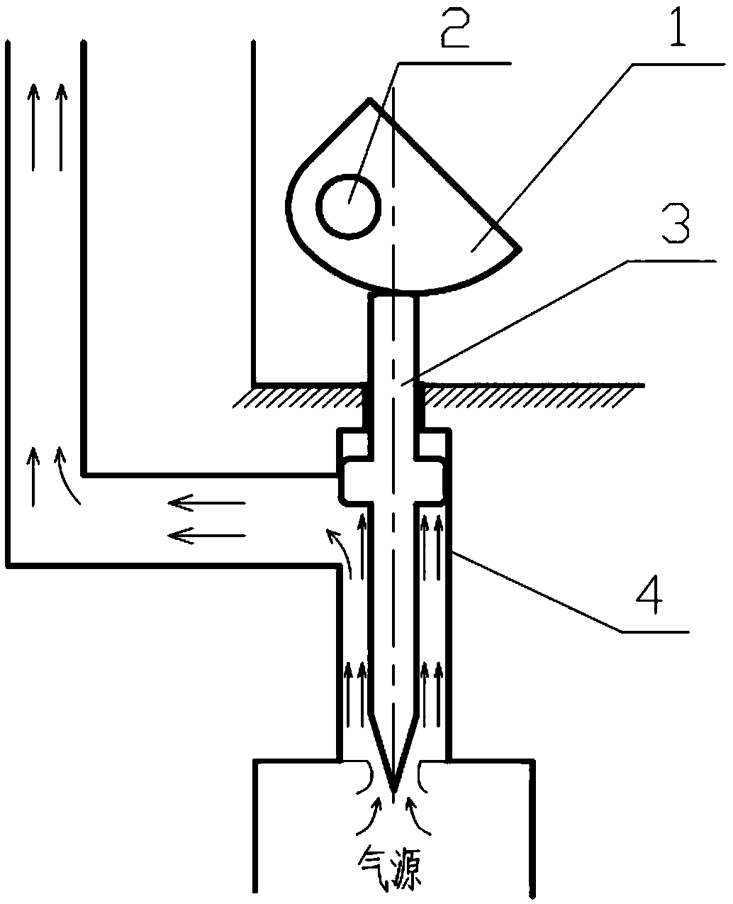
[0026] See details Figure 1a-Figure 1b , an optimal design method of an offset cam air intake control mechanism, adopting an offset cam structure in which the cam 1 and the camshaft 2 are integrated, and driving the thimble 3 to move linearly along the guide groove 4 through the cam surface to optimize the cam eccentricity Contact the curved surface with the thimble, so that the cam surface drives the thimble to meet the principles of thrust equivalence and eccentric load balance, and realize the function of small moment arm and large torque, which is easy to install in a narrow space. The specific design scheme is as follows:

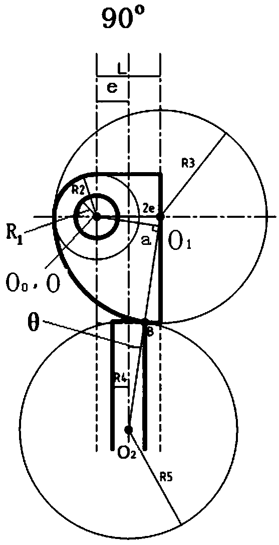
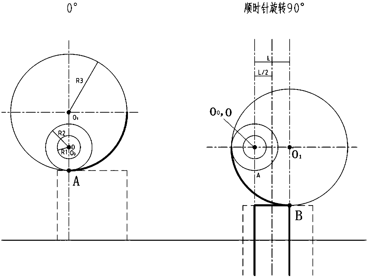
[0027] see attached figure 2 And attached image 3

[0028] 1. Determine the maximum stroke of the thimble

[0029] 1) Determine the camshaft cylinder radius R1 and the cam base circle radius R2 according to th...


PUM


Abstract

The invention relates to an optimization design method of an offset cam type air inlet control mechanism. The optimization design method is characterized in that an offset cam type structure with a cam and a cam shaft in an integral structure is used; a jacking pin is driven to do linear movement along a guide groove through the cam curve surface; a cam eccentric pitch and the jacking pin contact curve surface are optimized, so that the cam curve surface drives the jacking pin to meet the thrust equivalent and unbalance loading balance principle; the large-force arm and large-moment function is realized; the installation in a narrow space is convenient. The method has the beneficial effects that the curve surface-curve surface contact obtains the same thrust as the curve surface-plane contact through optimizing the jacking pin contact curve surface; the thrust equivalent principle is met; in addition, the reasonable jacking pin cylinder radius dimension can be obtained through enabling the jacking pin contact curve surface to adapt to the jacking pin cylinder radius change; the cam eccentric pitch and the jacking pin contact curve radius is selected, so that the pressure angle change amplitude is minimum; the symmetrical distribution along the jacking pin axial line is realized, the offsetting balancing principle is met; the small-force-arm large-moment function and the structure compactness requirements are met; the installation in the narrow space is convenient.

Description

technical field [0001] The invention belongs to an air bag inflation control method, in particular to a design method for implementing miniature high-pressure inflatable steel cylinder inflation control on an air bag by using an offset cam type air intake control mechanism. Background technique [0002] Leakage plugging and lifesaving of ships are important contents of navigation safety, and leak plugging equipment and lifesaving devices are mainly used to implement protection. Airbag leak plugging equipment and lifesaving devices have the advantages of light weight, rollable storage, and easy portability. Therefore, they have been widely valued and developed in recent years. Air bag plugging equipment is a new type of leak plugging device that uses air bags to plug leaks in hull breaches. Air bag life-saving devices include life jackets, life rafts, etc. The key to the technology of airbag leak-stopping equipment and life-saving devices is the air intake control of the air...

Claims


Application Information

Patent Timeline
Patent Type & Authority Patents(China)
IPC IPC(8): G06F17/50
CPCG06F30/17
Inventor 李敏堂
Owner MILITARY TRANSPORTATION RES INST OF PLA GENERAL LOGISTICS DEPT
Learn More