an explosion-proof torch
What is Al technical title?
Al technical title is built by PatSnap Al team. It summarizes the technical point description of the patent document.
A technology of torch and torch head, which is applied in the field of petrochemical industry, petroleum and oil shale mining, and can solve problems such as explosion, mixed gas backfire, and the torch cannot be recovered.
Active Publication Date: 2018-05-04
赵金岷
View PDF8 Cites 0 Cited by
Summary
Abstract
Description
Claims
Application Information
AI Technical Summary
This helps you quickly interpret patents by identifying the three key elements:
Problems solved by technology
Method used
Benefits of technology
Problems solved by technology
[0004] The purpose of the present invention is to provide an explosion-proof torch in order to solve the problem that the gas that cannot be recovered in the existing torch treatment, especially the mixed gas will flash back or even explode.
Method used
Image
Click on the blue label to locate the original text in one second.
Reading with bidirectional positioning of images and text.
Examples
Embodiment 1
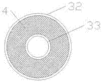
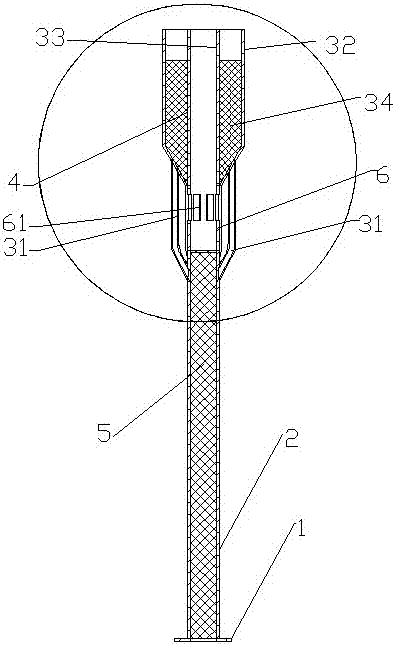
[0017] Example 1: see Figure 1-4 , a torch, comprising: an ignition device, a connecting flange 1, a mixed gas pipeline 2, a heat dissipation shunt pipe 31, and a torch head 3;
[0018] The lower part of the mixed gas pipeline 2 is provided with a connecting flange 1, and the upper part of the mixed gas pipeline 2 is closed;
[0019] The inside of the mixed gas pipeline 2 is filled with a low-temperature flame arresting net 5;
[0020] The torch head 3 is barrel-shaped, with a cooling gas passage 33 in the middle, which runs through up and down, and an annular cavity 34 with a closed lower end and an open upper end is formed between the torch head shell 32 and the cooling gas passage 33;
[0021] The interior of the annular cavity 34 is filled with a high-temperature fire-blocking net 4; a high-temperature fire-blocking net 4 and a low-temperature fire-blocking net 5;
[0022] The lower end of the torch head shell 32 is provided with a heat dissipation shunt pipe 31, and th...
Embodiment 2
[0026] Example 2: see Figure 1-4 , a torch, comprising: an ignition device, a connecting flange 1, a mixed gas pipeline 2, a heat dissipation shunt pipe 31, a torch head 3, a high-temperature fire-blocking net 4, and a low-temperature fire-blocking net 5;
[0027] The lower part of the mixed gas pipeline 2 is provided with a connecting flange 1, and the upper part of the mixed gas pipeline 2 is closed;
[0028] The inside of the mixed gas pipeline 2 is filled with a low-temperature flame arresting net 5;
[0029] The torch head includes a torch head shell 32 and a cooling gas passage 33;
[0030] The torch head 3 is barrel-shaped, with a cooling gas passage 33 in the middle, which runs through up and down, and an annular cavity 34 with a closed lower end and an open upper end is formed between the torch head shell 32 and the cooling gas passage 33;
[0031] The interior of the annular cavity 34 is filled with a high-temperature fire-blocking net 4;
[0032] The lower end o...
PUM
Abstract
The invention discloses an anti-explosion torch. The anti-explosion torch comprises a connecting flange, a gas mixing pipeline and a torch head. A cooling gas channel is arranged in the middle of the torch head and is vertically through. An annular cavity is defined by a shell of the torch head and the cooling gas channel. The annular cavity, heat dissipation flow division pipes and the gas mixing pipeline are sequentially connected and communicate with one another. The heat dissipation flow division pipes are annularly distributed. The gas mixing pipeline is filled with a low-temperature flame-arresting net. The annular cavity is filled with a high-temperature flame-arresting net. The cooling gas channel and the heat dissipation flow division pipes play a role in cooling. The low-temperature flame-arresting net and the high-temperature flame-arresting net can prevent an explosion caused by pipeline backfire in the combustion process. Once the explosion happens, cooling gas enters the explosion region, the high temperature generated due to the explosion is lowered through cooling, high pressure generated due to the explosion is relieved through the low-temperature flame-arresting net and the high-temperature flame-arresting net, and the pressure and the temperature of the gas mixing pipeline are within the normal range, so that the anti-explosion effect is achieved. Air inlets around a rectifying air inflow pipe are formed between the gas mixing pipeline and the torch head and matched with the heat dissipation flow division pipes to play a role in airflow adjustment and sound attenuation.
Description
technical field [0001] The invention belongs to the technical fields of petroleum and oil shale exploitation and petrochemical industry, and in particular relates to an explosion-proof torch. Background technique [0002] Flare is a special combustion facility used to deal with combustible gas and combustible toxic gas that cannot be recovered and reprocessed from petrochemical plants, refineries, chemical plants and coke ovens. The hydrocarbon gas and acid gas are combusted and discharged in time. The torch system is an important facility to ensure the safe production of the factory and reduce environmental pollution. The stable operation of the flare system plays a vital role in safe production. With the enlargement of refining and chemical equipment and the increase of refining complexity, the amount of flare gas entering the flare system in emergency situations increases, and the operation risk of the flare system increases. The operation and management of the flare sy...
Claims
Application Information
Patent Timeline
Application Date:The date an application was filed.
Publication Date:The date a patent or application was officially published.
First Publication Date:The earliest publication date of a patent with the same application number.
Issue Date:Publication date of the patent grant document.
PCT Entry Date:The Entry date of PCT National Phase.
Estimated Expiry Date:The statutory expiry date of a patent right according to the Patent Law, and it is the longest term of protection that the patent right can achieve without the termination of the patent right due to other reasons(Term extension factor has been taken into account ).
Invalid Date:Actual expiry date is based on effective date or publication date of legal transaction data of invalid patent.