Novel tail water tunnel ventilation hole structure

A tailrace tunnel and ventilation hole technology, which is applied in water conservancy projects, hydropower, hydropower stations, etc., can solve the problem of not being able to balance the minimum negative pressure and maximum positive pressure, and achieve remarkable results and relieve impact pressure. Effect

Active Publication Date: 2016-07-27
HOHAI UNIV
View PDF4 Cites 1 Cited by
  • Summary
  • Abstract
  • Description
  • Claims
  • Application Information

AI Technical Summary

Problems solved by technology

In the current design, the air hole area of ​​a fixed size is basically used, and the contradiction between the minimum negative pressure and the maximum positive pressure cannot be well balanced. The present invention uses a new air hole form, which is well coordinated Minimum negative pressure and instantaneous maximum positive pressure of tailrace tunnel

Method used


Image

  • Novel tail water tunnel ventilation hole structure
  • Novel tail water tunnel ventilation hole structure
  • Novel tail water tunnel ventilation hole structure

Examples


Embodiment

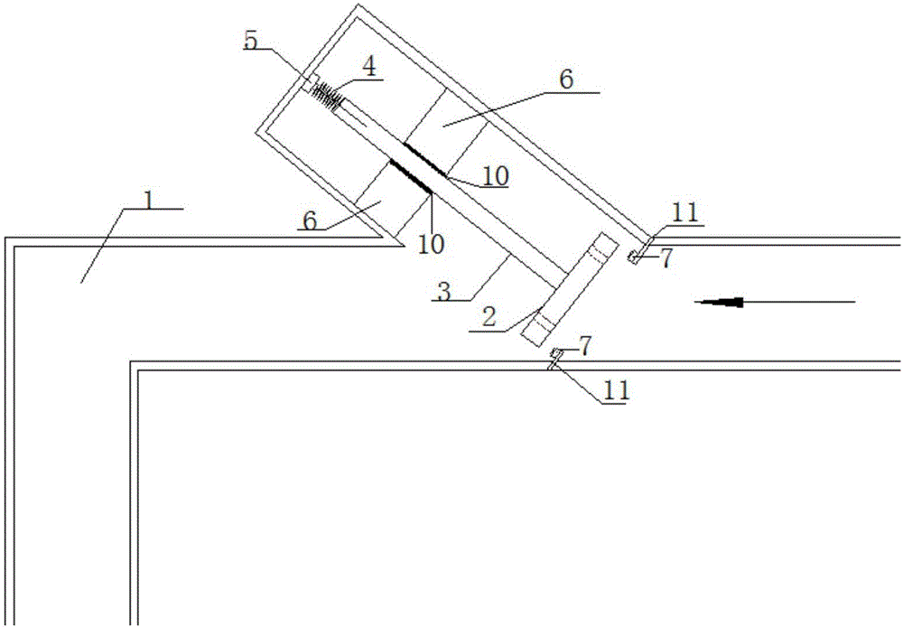
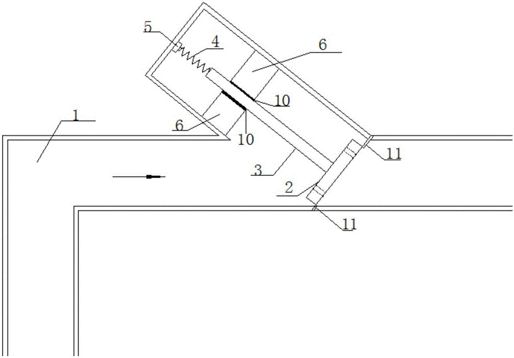
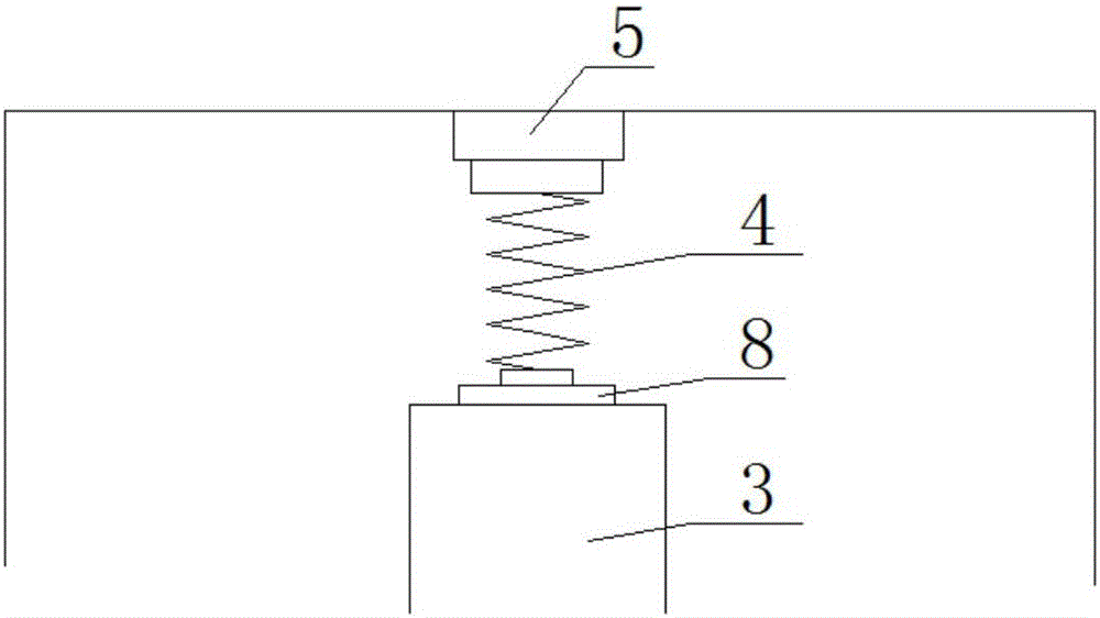
[0033] The novel tailrace tunnel ventilation orifice structure of this embodiment, such as figure 1 , figure 2 , image 3 , Figure 4 and Figure 5 As shown, when the movable baffle 2 is closed, the air flow can only pass through the reserved round hole 9 in the movable baffle 2, the movable connecting rod 3 is fixed with the movable baffle 2, and the annular anti-slip block body 6 is used to fix the movable connecting rod 3. direction. A movable baffle 2 is set at the ventilation hole 1. When the movable baffle 2 is opened, the movable connecting rod 3 slips sideways. A lubricating device 10 is arranged between the annular anti-slip block body 6 and the movable connecting rod 3. The spring buffer device 5 is used to protect The movable connecting rod 3, when the movable baffle 2 is pushed up by the air flow of the intake air, the movable connecting rod 3 moves accordingly, compressing the spring 4, at this time, the ventilation hole is full-area air intake; when the mova...


PUM


Abstract

The invention discloses a novel tail water tunnel ventilation hole structure. The structure comprises a ventilation hole, a movable baffle plate, a movable connecting rod, a spring, a buffer device, an annular antiskid block body and a clamping groove. The ventilation hole is a two-way ventilation hole; when negative pressure is generated in a tail water tunnel, air enters the ventilation hole from external, air currents can eject up the movable baffle plate, the movable baffle plate drives the movable connecting rod to move along the inclined upper side, and at this time, the movable baffle plate is totally opened, the intake area is maximal, the air replenishing speed is quicker, and the negative pressure of the tail water tunnel can be timely relieved; and when the tail water tunnel is exhausted, pressure of reverse air currents can enable the movable baffle plates to move along the inclined lower side, the movable baffle plate is engaged with the clamping groove, the ventilation hole is closed, the air currents are exhausted from round holes reserved in the movable baffle plate, and the exhaust speed is slower, so that the transient pressure is largely reduced when air masses are exhausted out of the hole. The structure can largely relieve the negative pressure in the tunnel in air suction and the collision pressure in air exhausting under the precondition of satisfying other safety and reliability requirements, and in particular, is prominent in effect for the tail water tunnel of a hydropower station and a city pipe network.

Description

technical field [0001] The invention relates to the technical field of water conservancy and hydropower engineering, in particular to a novel tailwater tunnel ventilation hole structure, which is suitable for hydropower station tailwater tunnels and urban pipe networks. Background technique [0002] In the early stage of the construction of a large-scale diversion-type hydropower station, a large-scale construction diversion tunnel is required, and the design often combines the construction diversion tunnel with the tail water system of the hydropower station. In the later stage of the project, part of the diversion tunnel is converted into a power generation tail water tunnel. When the water level of the downstream cascade reservoirs is close to the top of the tunnel, the initial pressure in the tailrace tunnel is small. When the power station transitions, the pressure and surge in the tailrace change drastically, which may lead to the tailrace tunnel at a higher position. ...

Claims


Application Information

Patent Timeline
Patent Type & Authority Applications(China)
IPC IPC(8): E02B9/06
CPCE02B9/06Y02E10/20
Inventor 俞晓东张健储善鹏刘甲春陈胜
Owner HOHAI UNIV
Why Eureka
Try Eureka