
Composite material grid conical shell fiber placing and winding integrated molding device

A composite material and forming device technology, which is applied in the field of composite mesh cone shell wire laying and winding integrated forming device, can solve the problems of difficult to accurately design the shell thickness and layup angle, and difficult to accurately control the layup thickness, etc. Achieve the effect of favorable molding quality control, convenient loading and unloading, and controllable winding tension

Active Publication Date: 2016-07-27
AEROSPACE RES INST OF MATERIAL & PROCESSING TECH +1
View PDF5 Cites 13 Cited by
  • Summary
  • Abstract
  • Description
  • Claims
  • Application Information

AI Technical Summary

Problems solved by technology

The development of automatic forming technology of composite material shell components in China is relatively late. At present, it can only realize the automatic forming of composite material skin components with a cross-section near the cylinder, and the forming of tapered (curved surface) composite components with variable cross-section still adopts the method of manual forming.
For grid shell components, only wet winding is used to form the grid shell, but its shell thickness and layer angle are difficult to accurately design, while the dry winding is used to form the grid shell, only the ribs are wound. , the skin is formed by a combination of winding and manual layup, and the thickness of the layup is also difficult to control accurately

Method used


Image

  • Composite material grid conical shell fiber placing and winding integrated molding device
  • Composite material grid conical shell fiber placing and winding integrated molding device
  • Composite material grid conical shell fiber placing and winding integrated molding device

Examples


Embodiment

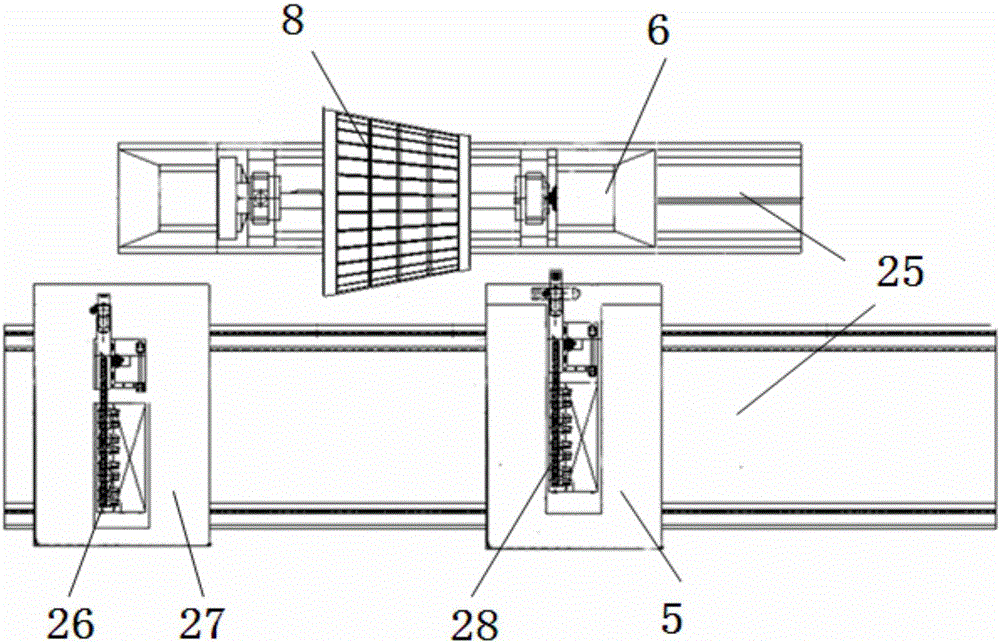
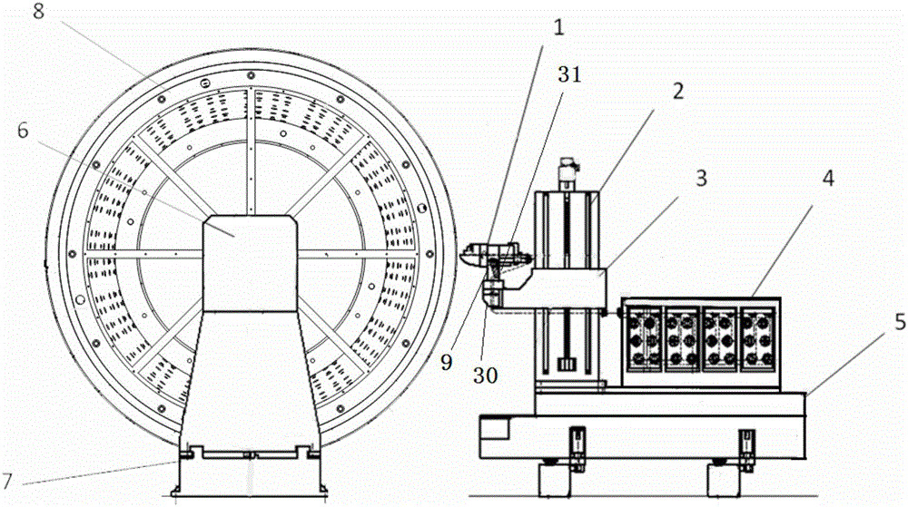
[0040] The integrated wire laying and winding forming device of the composite grid cone shell member includes a machine tool, a grid cone shell member mold, a spindle, an automatic wire laying device, a winding device, a wire laying trolley and a winding trolley; the machine bed is located on the foundation , the main shaft of the machine tool is installed on the bed; during the forming process, the grid cone shell component mold is clamped on the main shaft; the automatic wire laying device is installed on the wire laying trolley platform, and the winding device is installed on the winding trolley. Both the trolley and the winding trolley are seated on the foundation, and each can move horizontally and laterally.

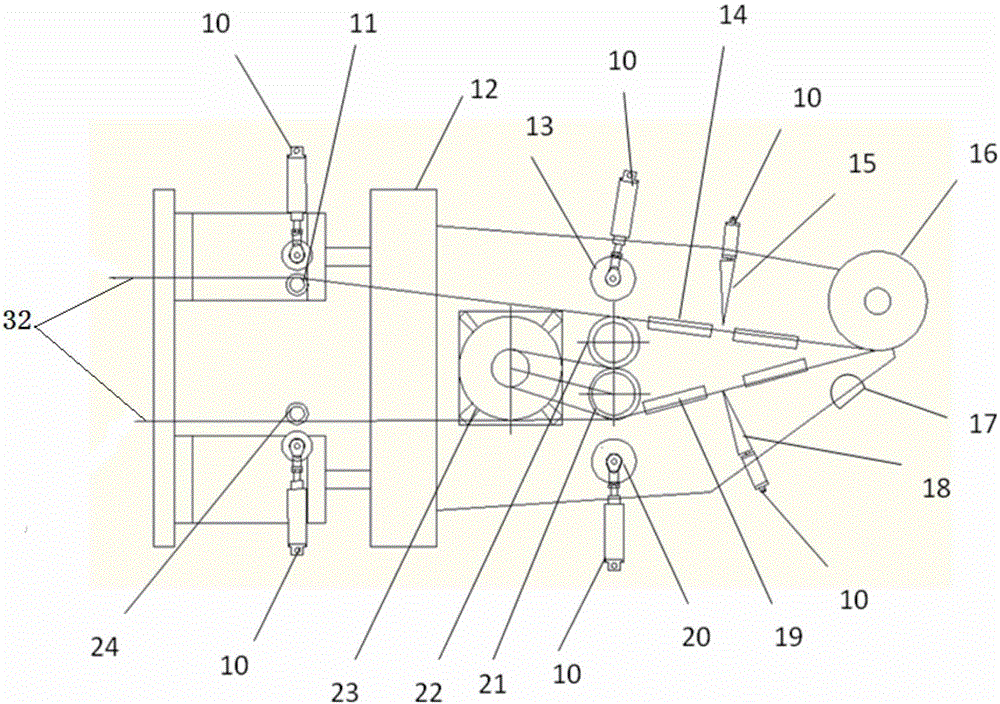
[0041] The automatic laying device includes automatic laying head, laying head rotation mechanism, laying pitching mechanism, laying head yaw mechanism, vertical mechanism, outrigger mechanism and yarn box; the vertical mechanism and yarn box are directly installed ...


PUM

PropertyMeasurementUnit
diameteraaaaaaaaaa

Abstract

The invention discloses a composite material grid conical shell fiber placing and winding integrated molding device, and relates to the technical field of composite material preparation. The device comprises a grid conical shell component mold, a winding device, a winding trolley, a fiber placing device and a fiber placing trolley. The integrated molding device not only can be used for finishing the winding of grid ribs, but also can be used for finishing the fiber placement molding of stressed-skin constructions, and has a tow resin temperature control ability to realize control over the prepreg tow viscosity in the transmission process; a heating system is configured in a placing head to enable prepreg tows to be heated, so that the prepreg tows have a certain viscosity and then the process requirements are satisfied. The device disclosed in the invention can be applied to composite material grid conical shell components, and is good in molding quality, high in placing precision, good in product quality and high in manufacture efficiency; an automatic fiber placing system and a grid rib winding system are integrated in a set of equipment, so that the high-efficiency and high-quality composite integrated molding of the composite material grid conical shell components is realized.

Description

technical field [0001] The invention relates to the technical field of composite material preparation, in particular to a composite material grid cone shell wire laying and winding integrated molding device. Background technique [0002] The automatic wire laying technology combines the advantages of fiber winding and automatic tape laying technology. It can cut the tow at any time according to the change of the surface shape of the component, and continue to transport the tow when necessary. It is suitable for components with complex shapes such as concave curved surfaces, convex curved surfaces, and variable cross-sections. forming. Composite conical shell components formed by automatic wire laying technology abroad include American Minotaur rocket fairings, American space shuttle cryogenic tanks, and Atlas 5 launch vehicle load adapters. [0003] The development of automatic forming technology of composite material shell components in China is relatively late. At present...

Claims


Application Information

Patent Timeline
Patent Type & Authority Applications(China)
IPC IPC(8): B29C70/38B29C53/56
CPCB29C53/56B29C70/382B29C70/384
Inventor 张建宝刘伟张毅郭鸿俊蒋文革
Owner AEROSPACE RES INST OF MATERIAL & PROCESSING TECH
Learn More