Metasurface-based Four-beam Microstrip Transmissive Array Antenna and Its Design Method

A metasurface and array antenna technology, applied in the direction of antenna, waveguide horn, radiation element structure, etc., can solve the problems of large loss, complex manufacturing and space application, and high cost

Active Publication Date: 2018-06-08
AIR FORCE UNIV PLA
View PDF6 Cites 0 Cited by
  • Summary
  • Abstract
  • Description
  • Claims
  • Application Information

AI Technical Summary

Problems solved by technology

The synthesis method of traditional multi-beam antennas is based on horn feed arrays or large phased arrays, often relying on multi-port multi-beam forming feed networks, complex fabrication and space applications, high loss, and high cost

Method used


Image

  • Metasurface-based Four-beam Microstrip Transmissive Array Antenna and Its Design Method
  • Metasurface-based Four-beam Microstrip Transmissive Array Antenna and Its Design Method
  • Metasurface-based Four-beam Microstrip Transmissive Array Antenna and Its Design Method

Examples


Embodiment Construction

[0035] Four-beam transmission array antenna embodiment:

[0036] like Image 6 As shown, the length of the waveguide is a =22.86 mm, width is b =10.16 mm, the horn opening diameter is A * B =44*24mm 2 , the overall height is L =30 mm, a, b is the aperture size of the standard X-band waveguide BJ-100, A , B and L Determined based on impedance matching and antenna aperture size optimization.

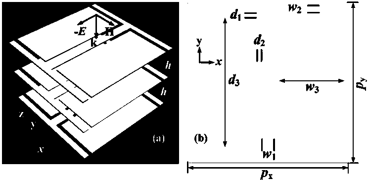
[0037] Among them, the structural parameters of the metasurface microstrip transmission array unit are p x = p y =10mm, w 1 =0.8mm, w 2 =0.5mm, w 3 =4.05 mm, d 1 = d 2 =0.3 mm and d 3 =8mm.

[0038] The central operating frequency of the transmission array antenna of the present invention is f 0 =9.6GHz, N =25, D =250 mm, F =150mm, the elevation angles of the four beams are θ =40°, the azimuth angles are φ 1 =0°, φ 2 =90°, φ 3 =180° and φ 4 =270°.

[0039] For verifying the correctness of the design method of the present invention, Figure 7 T...


PUM


Abstract

The invention belongs to the technical field of microstrip transmission array antennas, in particular to a metasurface-based four-beam microstrip transmission array antenna and a design method thereof. The four-beam microstrip transmission array antenna designed by the present invention is composed of a horn feed source and a metasurface microstrip transmission array; wherein, the horn feed source is composed of a waveguide and a horn opening; the distance between the horn opening and the metasurface microstrip array is F , the caliber of the metasurface microstrip array is D*D; the metasurface microstrip array is composed of N*N metasurface transmission units; the metasurface transmission unit consists of 3 layers of identical composite metal structures and 2 The composite metal structure is composed of an I-shaped structure and completely symmetrical metal patches, which are used to form two transmission mode couplings in the same plane, thereby reducing the unit resonance frequency and increasing the phase response slope and phase accumulation. . The advantages of the four-beam microstrip transmission array antenna designed in the present invention are low side lobe, high gain, balanced beam, light weight, low cost and easy assembly and integration.

Description

technical field [0001] The invention belongs to the technical field of microstrip transmission array antennas, in particular to a four-beam microstrip transmission array antenna and a design method thereof. Background technique [0002] Multi-beam antennas have the advantages of flexible control of the number and shape of beams, and quick beam scanning. They are widely used in electronic countermeasures, satellite communications, multi-target radar systems, and multi-channel intelligent communications. Traditional multi-beam antenna synthesis methods are based on horn feed arrays or large phased arrays, often relying on multi-port multi-beam forming feed networks, which are complex in fabrication and space application, with high loss and high cost. There are three types of existing multi-beam technologies: lens type, reflector type and phased array type. Microstrip array antenna combines the characteristics of array antenna and parabolic reflector, and has many advantages s...

Claims


Application Information

Patent Timeline
Patent Type & Authority Patents(China)
IPC IPC(8): H01Q1/38H01Q13/02H01Q13/08
CPCH01Q1/38H01Q13/02H01Q13/08
Inventor 许河秀蔡通王光明梁建刚
Owner AIR FORCE UNIV PLA
Why Eureka
Try Eureka